Roller kiln with double-layer smoke exhaust channel structure

A technology of smoke exhaust channel and roller table, which is applied in the field of architectural ceramic kilns, can solve the problems of increasing energy consumption of kilns, and achieve the effects of saving energy consumption, reducing natural gas consumption, and increasing temperature

Active Publication Date: 2022-02-18
DONGGUAN CITY WONDERFUL CERAMICS IND PARK +2
View PDF0 Cites 0 Cited by
  • Summary
  • Abstract
  • Description
  • Claims
  • Application Information

AI Technical Summary

Problems solved by technology

[0003] The purpose of the present invention is to provide a roller kiln with a double-layer smoke exhaust channel structure that solves the problem of increasing energy consumption of the kiln as the kiln lengthens.

Method used


Image

  • Roller kiln with double-layer smoke exhaust channel structure
  • Roller kiln with double-layer smoke exhaust channel structure

Examples


Embodiment Construction

[0018] The present invention will be described in further detail below in conjunction with accompanying drawing:

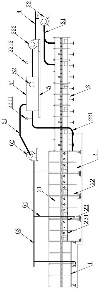
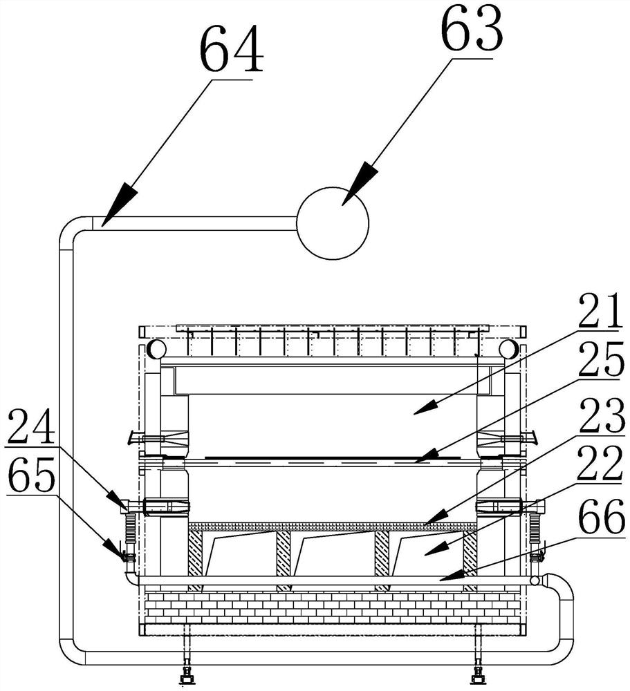
[0019] see figure 1 As shown, a roller kiln with a double-layer smoke exhaust channel structure includes a firing section kiln body 1, an oxidation section kiln body 2, and a smoke exhaust section kiln body 3. The smoke exhaust section kiln body 3 is externally connected with a row The smoke air duct 31, the exhaust air duct 31 is connected with the smoke exhaust main air duct 4 through the first exhaust fan 32, the smoke exhaust main air duct 4 is connected with the drying kiln, and the inside of the oxidation section kiln body 2 The smoke exhaust channel is divided into upper and lower layers by the refractory material partition 21 located below the ceramic roller 25. The refractory material partition 21 is provided with several smoke inlets 231 at intervals. The upper smoke exhaust channel 21 and the lower smoke exhaust channel The channel 22 communicates with...


PUM


Abstract

The invention relates to a roller kiln with a double-layer smoke exhaust channel structure, which includes a kiln body in a firing section, an oxidation section kiln body, and a smoke exhaust section kiln body. The smoke exhaust section kiln body is connected with a smoke exhaust duct. The smoke exhaust duct is connected to the main exhaust duct through the first exhaust fan, and the main exhaust duct is connected to the drying kiln. Layer, the partition board is provided with several flue gas inlets at intervals, the upper layer smoke exhaust channel communicates with the lower layer smoke exhaust channel through the flue gas inlet, the upper layer smoke exhaust channel communicates with the smoke exhaust section kiln body, the The end of the smoke exhaust channel in the lower layer is provided with an auxiliary smoke exhaust duct, and the other end of the auxiliary smoke exhaust duct passes through the flue gas heat exchanger installed on the steel structure platform and passes through the second smoke exhaust fan installed on the steel structure platform and Smoke exhaust main air duct connection.

Description

technical field [0001] The invention relates to the technical field of building ceramic kilns, in particular to a roller kiln with a double-layer smoke exhaust channel structure. Background technique [0002] With the continuous pursuit of large production capacity and low cost in the architectural ceramics industry, the length of firing kilns has been continuously increased, and kilns with a length of 500 to 600 meters have been put into production and application one after another. As the length of the kiln increases, the distance from the preheating smoke exhaust section of the kiln head to the firing section also increases. During the ceramic firing process, a large amount of high-temperature flue gas will be generated in the high-temperature firing section of the kiln, which requires Exhaust through the exhaust fan in the preheating exhaust section, the longer the distance is, the greater the resistance of the exhaust, the exhaust fan can only extract the smoke by incre...

Claims


Application Information

Patent Timeline
Patent Type & Authority Patents(China)
IPC IPC(8): F27B9/02F27B9/24F27B9/36F27B9/40F27D17/00F23L15/00
CPCF27B9/02F27B9/2407F27B9/36F27B9/40F27D17/004F23L15/00F27B2009/3661Y02E20/34
Inventor 林育成叶佐辉
Owner DONGGUAN CITY WONDERFUL CERAMICS IND PARK
Why Eureka
Try Eureka