High-heat-resistance coil gun armature structure

A coil gun, high heat-resistant technology, applied in the field of coil guns, can solve the problems that the structure design of the coil gun armature is rarely mentioned, and achieve the effect of weakening the eddy current effect, increasing the outlet speed and reducing the quality.

Active Publication Date: 2020-08-14
XI AN JIAOTONG UNIV
View PDF11 Cites 1 Cited by
  • Summary
  • Abstract
  • Description
  • Claims
  • Application Information

AI Technical Summary

Problems solved by technology

[0004] At present, most of the relevant patents in the field of coil guns mainly focus on the application of the coil gun structure and the control of the coil gun, and rarely mention the design of the coil gun armature structure

Method used


Image

  • High-heat-resistance coil gun armature structure
  • High-heat-resistance coil gun armature structure
  • High-heat-resistance coil gun armature structure

Examples


Embodiment 1

[0037] In step (1), high-purity pure copper with high-density twins is prepared by pulse electrodeposition using copper sulfate (CuSO4) as the electrolyte. The average grain size is 400nm, the twin sheet length is between 100nm and 1000nm, and the average twin sheet thickness is 15nm.

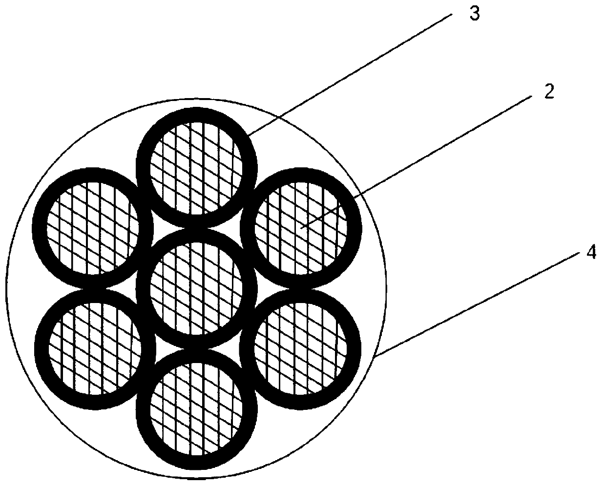
[0038] Step (2), adopt the nano-twinned copper in the step (1) to make copper wire, the cross-sectional diameter of copper wire should be slightly less than 2 times of current skin depth in the armature coil, guarantee that the whole cross-section of copper wire can play To achieve effective conduction, the diameter of the copper wire should be less than 2.1mm when the excitation current is 1000hz. Such as figure 1 As shown in 2, where 2 is the cross section of the copper wire, and also the actual distribution of the current in the copper wire.

[0039] In step (3), wrap a layer of polyimide (PEEK) or C / CSI composite material on the outside of the copper wire in step (2), so as to prevent cur...

Embodiment 2

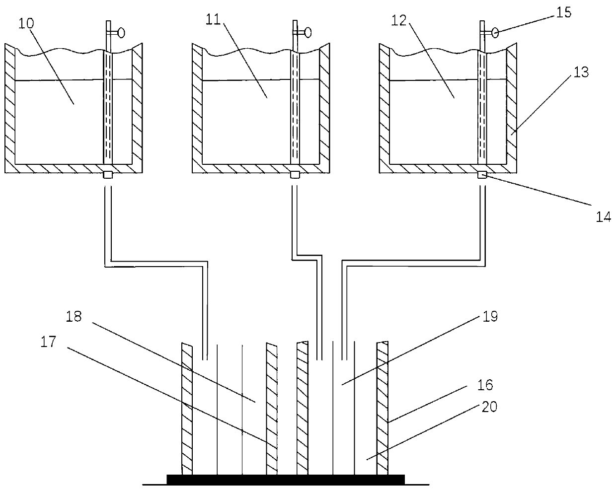
[0045] Step (1), in different ladles, hold alloy liquids with different composition ratios, such as image 3 As shown, 13 is a ladle, 10 is a copper alloy liquid with an aluminum content of 7%, 11 is a red copper alloy liquid, and 12 is a copper alloy liquid with an aluminum content of 2%.

[0046] In step (2), the alloy liquid with different components in step (1) is cast in a multi-nozzle method, and the mold is cast, such as image 3 As shown, 14 is the water outlet, 15 is the control valve, 16 is the outside of the mold, 17 is the inside of the mold, 18, 19, and 20 are respectively the inner casting area, the middle casting area and the outer casting area. Region 20 is cast using molten alloy 10 , region 18 is cast using molten alloy 11 , and region 19 is cast using molten alloy 12 . After the casting is completed, a layered annular alloy ingot is formed, the resistivity of the material inside the alloy ingot is low, and the resistivity of the material outside the alloy i...


PUM

PropertyMeasurementUnit
Diameteraaaaaaaaaa
Diameteraaaaaaaaaa
Average sizeaaaaaaaaaa

Abstract

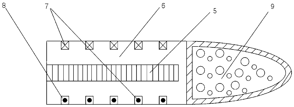
The invention discloses two high-heat-resistance coil gun armature structures with simple structures. The first coil gun armature is characterized in that a plurality of armature coils adopt a parallel winding structure; insulation treatment is carried out on the parallel winding copper wire of the coils; a magnetic conductive iron core is arranged in an armature; the magnetic conductive iron coreand the armature coils are mounted on the inner side and the outer side of a ceramic heat-conducting structure body; the front end of the armature is a warhead part which can be filled with combat ammunition; and the coil gun armature has the characteristics of high heat resistance, low excitation requirement, large thrust, light weight and the like. The second coil gun armature is of an annularsolid armature structure, an armature cavity is used for loading ammunition and electronic equipment; and the armature is characterized in that the distribution rule of the resistivity of the armaturematerial along the radial direction of the armature is that the resistivity of the material close to the outer side of the armature is high, the resistivity of the material close to the inner side ofthe armature is low, and the distribution of the armature material can guide induced current to be distributed to the deep layer of the armature so as to avoid armature ablation.

Description

technical field [0001] The invention belongs to the field of coil guns, and in particular relates to two high heat-resistant coil gun armature structures. Background technique [0002] The development of modern warfare has put forward new requirements for the speed of weapon replacement. As a new type of weapon, coil guns have the characteristics of high firing speed, long firing distance, no smoke during firing, and controllable energy, which are more and more favored by various countries. The principle of the coil gun is very simple. Appropriate currents are passed through the drive coil and the armature coil respectively, so that the magnetic fields generated in the drive coil and the armature coil repel or attract each other, and the drive coil is fixed. The armature coils accelerate and eventually fire the armature at a very high velocity. [0003] The concept of coil guns has been proposed very early, but the backwardness of manufacturing technology has restricted the...

Claims


Application Information

Patent Timeline
IPC IPC(8): F41B6/00F41F1/00
CPCF41B6/00F41F1/00Y02E40/60
Inventor 娄建勇彭建东王旭明徐虹钱佳豪黄立秋陈腾江中毅
Owner XI AN JIAOTONG UNIV
Why Eureka
Try Eureka