Sound field separation method based on least square method of Helmholtz equation

A technology of least squares method and separation method, which is applied in the measurement of ultrasonic/sonic/infrasonic waves, measurement devices, instruments, etc., can solve the problems of complex implementation process, high acquisition cost, and much information required, and achieve high separation accuracy and reduce The effect of reducing the workload and reducing the collection cost

Active Publication Date: 2020-08-14
HARBIN ENG UNIV
View PDF25 Cites 2 Cited by
  • Summary
  • Abstract
  • Description
  • Claims
  • Application Information

AI Technical Summary

Problems solved by technology

As can be seen from the above three methods, the existing methods all use the composite measurement value as the input value of the sound field separation method, that is, to obtain one kind of physical informati

Method used


Image

  • Sound field separation method based on least square method of Helmholtz equation
  • Sound field separation method based on least square method of Helmholtz equation
  • Sound field separation method based on least square method of Helmholtz equation

Examples


Embodiment

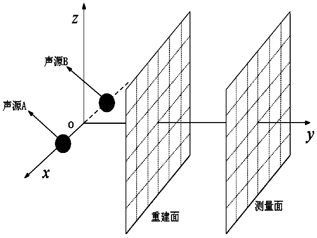
[0064] Such as figure 1 , in this embodiment, sound source A and sound source B are on the same side of the measurement surface, wherein sound source A is the main sound source, and sound source B is the noise source. In the radiated sound field formed by sound source A and sound source B, the outside It is the measurement surface, the distance from the sound source is d0, and the one closer to the sound source (d1) is the reconstruction surface. There are measurement points distributed in a grid pattern on the measurement surface and the reconstruction surface, and there are at least 5 wavelengths corresponding to the highest analysis frequency. grid points. Group the measured sound pressure into groups S1 and S2, decompose the sound pressure at each measuring point through the transfer relationship between the two groups of sound pressures, and obtain the individual response of the sound source A at the measuring point to complete In the separation of the measurement surfac...


PUM


Abstract

The invention aims at providing a sound field separation method based on a least square method of a Helmholtz equation. The sound field separation method comprises the following steps: acquiring a sound pressure on a measurement surface; resampling the sound pressure on the measurement surface to obtain different measuring point groups; decomposing the sound pressures generated by a sound source Aand a sound source B at each measuring point according to a sound pressure expansion formula in an HELS acoustic holography method, and establishing a transmission relationship between the sound pressures of the two sound sources on the measurement surface; establishing a transfer matrix between the measurement surface and the sound source surface; and performing singular value decomposition on the transfer matrix to obtain the sound pressure generated by the sound source A on the measurement surface or any position, thereby realizing sound field separation. According to the invention, the single measurement surface and the HELS method are used for sound field separation and reconstructionand only the sound pressure data of the single measurement surface need to be collected, so that thecollection workload and the collection cost are reduced; the number of needed measurement points is small, the calculation efficiency is high, and the implementation mode is simple.

Description

technical field [0001] The invention relates to a noise control method, in particular to a sound field separation method. Background technique [0002] In actual engineering measurement, there are often interference sources near the object to be measured. In order to analyze the radiation characteristics of the target sound source, it is necessary to separate the sound field. The existing sound field separation methods are divided into the following categories according to the measurement methods: (1) separation based on double-layer sound pressure measurement surfaces; (2) separation based on double-layer particle velocity measurement surfaces; (3) separation based on single-layer sound pressure- Particle velocity measurement surface separation. It can be seen from the above three methods that all the existing methods use the composite measurement value as the input value of the sound field separation method, that is, to obtain one kind of physical information on two measu...

Claims


Application Information

Patent Timeline
IPC IPC(8): G01H17/00
CPCG01H17/00
Inventor 肖友洪陈艺凡姜来旭段宇华冯明芳
Owner HARBIN ENG UNIV
Why Eureka
Try Eureka