Current parameter calibration system and method based on standard electromagnetic valve and oscilloscope
A technology of current parameter and calibration system, applied in instruments, measuring electrical variables, measuring devices, etc., can solve problems such as damage to special measuring equipment, and achieve the effect of simple structure, simple circuit structure, and accurate calibration results
- Summary
- Abstract
- Description
- Claims
- Application Information
AI Technical Summary
Problems solved by technology
Method used
Image

Examples
Embodiment Construction
[0029] Below in conjunction with the accompanying drawings and specific embodiments, the specific implementation of the present invention, such as the various components involved, the mutual position and connection relationship between each part, the function and working principle of each part, etc. will be further described in detail.
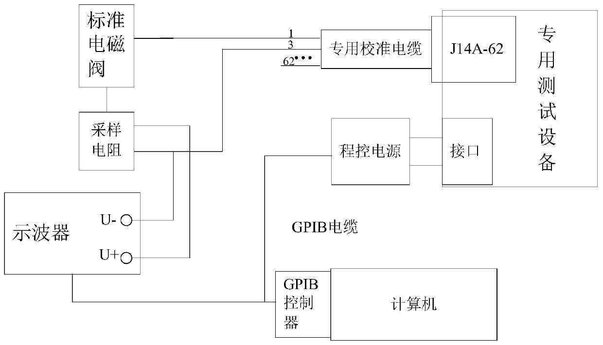
[0030] from figure 1 It can be seen that the current parameter calibration system based on standard solenoid valves and oscilloscopes in this embodiment mainly includes standard solenoid valves, sampling resistors, oscilloscopes, GPIB controllers, programmable power supplies, dedicated calibration cables, computers and host computer software. The special test equipment to be calibrated includes 50 sampling channels, and the dedicated calibration cable is a multi-core cable, the number of cable cores corresponds to the number of sampling channels, and one of the cable cores is a common cable core.
[0031] The program-controlled power supply, t...
PUM
 Abstract
Description
Claims
Application Information