
Fuel cell flow field structure, cathode plate, fuel cell bipolar plate, and fuel cell

A fuel cell and cathode plate technology, which is applied to fuel cells, circuits, electrical components, etc., can solve the problems of difficult manufacturing processes, related mechanisms are yet to be studied, and it is difficult to change the water adhesion to the wall of the flow channel, so as to improve the flow rate. Tao effect

Inactive Publication Date: 2020-08-14
擎能动力科技(苏州)有限公司
View PDF1 Cites 0 Cited by
  • Summary
  • Abstract
  • Description
  • Claims
  • Application Information

AI Technical Summary

Problems solved by technology

[0009] For the coating method, the focus of its technology research and development is the coating (how to improve its hydrophobicity), however, this technical route is not particularly ideal
[0010] For the microstructure method, the microstructure is at the nm level, and the manufacturing process is difficult; and the related mechanism remains to be studied
[0011] For the flow channel design method, it is difficult to change the problem of moisture sticking to the wall of the flow channel

Method used


Image

  • Fuel cell flow field structure, cathode plate, fuel cell bipolar plate, and fuel cell
  • Fuel cell flow field structure, cathode plate, fuel cell bipolar plate, and fuel cell
  • Fuel cell flow field structure, cathode plate, fuel cell bipolar plate, and fuel cell

Examples


Embodiment 1

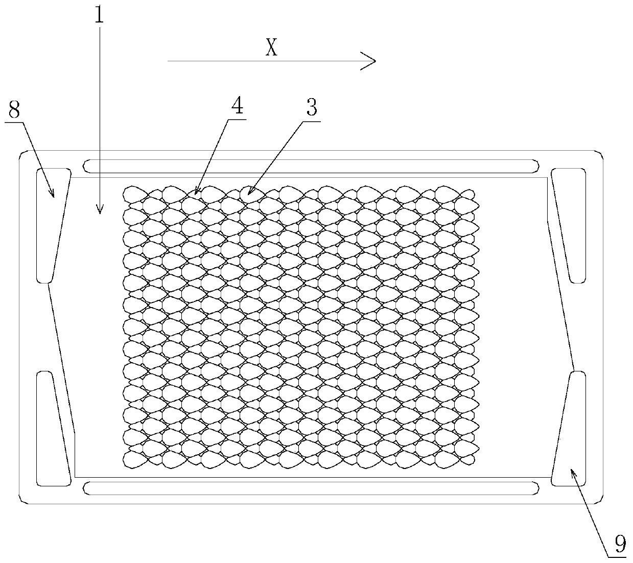
[0082] Embodiment 1, a fuel cell bipolar plate, which includes: a cathode plate 1, an anode plate;

[0083] Wherein, the cathode plate 1 (using a rectangular metal plate) is provided with an air inlet 8 and an air outlet 9, and the air inlet 8 and the air outlet 9 are arranged at the corners of the cathode plate 1, and the air inlet 8 and the air outlet 9 are opposite Corner line setting;

[0084] Wherein, the middle part of the cathode plate 1 is provided with a flow field structure;

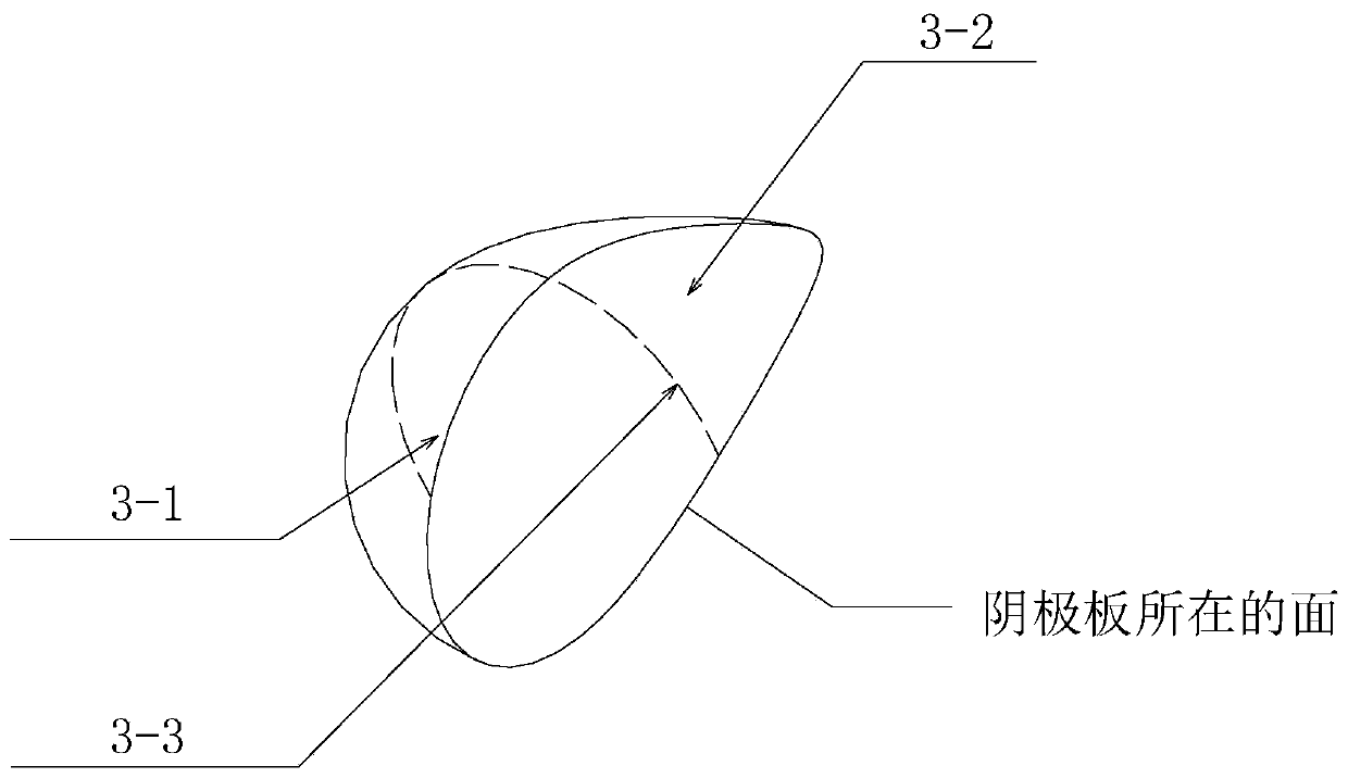
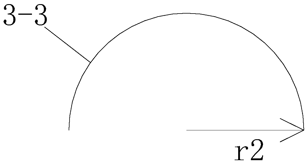
[0085] The flow field structure includes: an array of semi-droplet-shaped projections on the cathode plate, and an array of semi-droplet-shaped depressions on the cathode plate;

[0086] The cathode plate semi-drop-shaped projection array includes: several cathode plate semi-drop-shaped projections, and the cathode plate semi-drop-shaped projections are arranged in a quincunx shape;

[0087] The array of semi-drop-shaped depressions on the cathode plate includes: several semi-drop-shaped depr...

Embodiment 2

[0118] Embodiment two: if Figure 7-8 As shown, a plurality of first flow guide partitions 14 are arranged on the air inlet 8 side of the cathode plate, Figure 8 is in Figure 7 Improvements are made on the basis of the above, and a part of the first air guiding baffle 14 is arranged in an arc shape, so that the tail end of the first air guiding baffle 14 is parallel to the X direction, and furthermore, the air flow direction is also in the X direction.

[0119] Compared with the first embodiment, the second embodiment is more in line with the aerodynamic design.

[0120] A computer simulation test was carried out for the scheme of Example 2, as shown in Figure 9-11: when equilateral triangles are distributed, at different heights from the cathode plate, the air flows in the flow gap relatively uniformly, and no turbulent flow occurs. Phenomenon.


PUM


Abstract

The invention discloses a fuel cell flow field structure, a cathode plate, a fuel cell bipolar plate and a fuel cell, belongs to the technical field of new energy, and aims to improve the stability ofthe fuel cell. The fuel cell flow field structure is characterized by comprising a cathode plate semi-drop-shaped bulge array and a cathode plate semi-drop-shaped recess array, the cathode plate semi-drop-shaped bulge array comprises a plurality of cathode plate semi-drop-shaped bulges, and the cathode plate semi-drop-shaped bulges are arranged in a triangular shape; the cathode plate semi-drop-shaped recess array comprises a plurality of cathode plate semi-drop-shaped recesses, and the cathode plate semi-drop-shaped recesses are arranged in a triangular shape; and the cathode plate semi-drop-shaped bulge array and the cathode plate semi-drop-shaped recess array are arranged in a staggered manner.

Description

technical field [0001] The invention relates to the technical field of new energy vehicle fuel cells, in particular to a fuel cell flow field structure, a cathode plate, a fuel cell bipolar plate, and a fuel cell. Background technique [0002] A fuel cell is a device that generates electricity through a chemical reaction between hydrogen and air. It is the core component of a new energy vehicle, and its performance is directly related to the core performance of the new energy vehicle, such as mileage and acceleration performance. [0003] The bipolar plate (Bipolar Plate, BP) (also known as: flow field plate), is one of the core components of the proton exchange membrane fuel cell, and is the "skeleton" in the stack, which is stacked with the membrane electrode to form a stack. In the fuel cell, it plays the role of supporting, collecting current, providing channels for cooling liquid, separating oxidant and reducing agent, etc. [0004] According to https: / / www.autosaceplu...

Claims


Application Information

Patent Timeline
IPC IPC(8): H01M8/0258H01M8/0265
CPCH01M8/0258H01M8/0265Y02E60/50
Inventor 尹丛勃宋和国陈雷裴满许仁涛黄德永任军华何明宇
Owner 擎能动力科技(苏州)有限公司
Learn More