Primary pulp diluting device for anti-radiation fabric

A dilution device and anti-radiation technology, which is applied to mixers with rotating stirring devices, transportation and packaging, mixers, etc., can solve the problems of low dilution efficiency, substandard concentration, uneven mixing of raw pulp and diluted liquid, etc. To achieve the effect of improving the efficiency of dilution, uniform concentration, and improving the discharge efficiency

Inactive Publication Date: 2020-08-18
合肥克拉伦斯科技有限公司
View PDF10 Cites 0 Cited by
  • Summary
  • Abstract
  • Description
  • Claims
  • Application Information

AI Technical Summary

Problems solved by technology

[0003] During the production and processing of anti-radiation fabrics, various raw material pulps, that is, raw pulps, are needed. During the production process, the concentration of raw pulps is prone to fail to meet the standard. It is necessary to dilute the concentration of the raw pulps to meet the standards. The applicant has developed A puree dilution device, which adopts the division form of the puree area and the dilution area for dilution, but during dilution, the entry angle of the original pulp from the original pulp area into the dilution area is fixed, which is easy to cause the original pulp Uneven mixing with diluent, low dilution efficiency

Method used


Image

  • Primary pulp diluting device for anti-radiation fabric
  • Primary pulp diluting device for anti-radiation fabric
  • Primary pulp diluting device for anti-radiation fabric

Examples


Embodiment 1

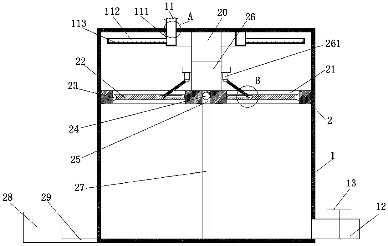
[0030] see Figure 1-3 , a raw pulp dilution device for radiation-proof fabrics, comprising a raw pulp tank 1, the upper end of the raw pulp tank 1 is provided with a feed pipe 11 for feeding, and one side of the bottom of the raw pulp tank 1 is provided with an outlet for discharging The material pipe 12, and the original slurry tank 1 is provided with a dilution plate 2 that matches the original slurry tank 1 and can slide up and down and rotate, and the dilution plate 2 is provided with a plurality of through-type dilution tanks 21, the dilution The tank 21 is provided with a sealing cover 22 that can be opened and closed and is used for sealing the dilution tank 21. The bottom of the dilution pan 2 is provided with a communication hole 25 for the up and down communication of the dilution pan 2. The upper end of the dilution pan 2 is provided with a plurality of uniform Distributed aeration pipes 24, the aeration pipes 24 are provided with evenly distributed aeration holes ...

Embodiment 2

[0036] The same as embodiment 1 is not repeated, and the difference with embodiment 1 is:

[0037] see Figure 4-5, the material distribution box 111 is an annular groove with an open upper end, and the inner wall of the puree tank 1 located at the upper end of the material distribution box 111 is provided with a material matching with the material distribution box 111 and sliding with the material distribution box 111 Connected distribution trough 116, the inner side walls of the distribution chute 116 are provided with an annular clamping groove 115, the clamping groove 115 is provided with a clamping plate 114 that matches the clamping groove 115 and is slidingly connected. The inner wall of the clamping plate 114 is fixedly connected with the corresponding outer wall of the distribution box 111 .

[0038] Further, the distributing pipe 112 is symmetrically distributed on the outside of the distributing box 111 with the distributing box 111 as the center, and the distribut...

Embodiment 3

[0041] The same as embodiment 1 is not repeated, and the difference with embodiment 1 is:

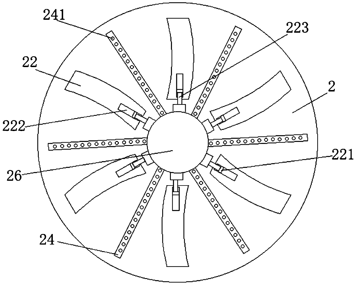
[0042] see Figure 6-7 , the dilution tanks 21 are distributed centrally symmetrically with the center of the dilution plate 2 as the center, and the two sides of the dilution tanks 21 are arc-shaped, and the dilution tanks 21 are distributed on the dilution plate 2 in the shape of fan blades.

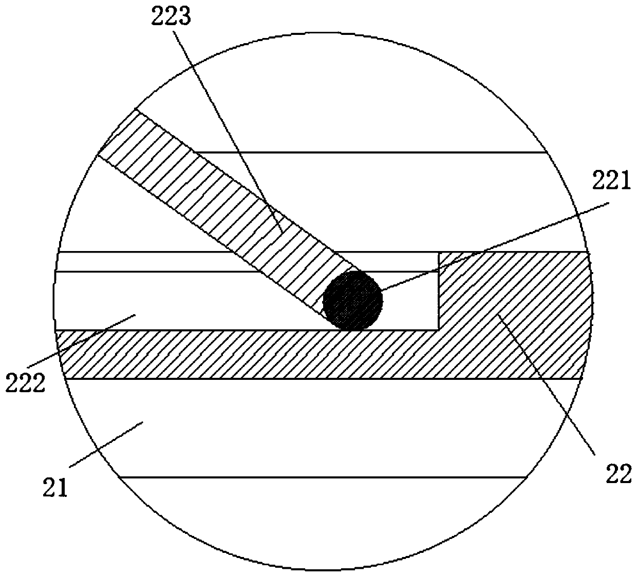
[0043] Further, the cross-sections of the two side surfaces of the dilution tank 21 are inclined, one side of the dilution tank 21 is provided with a first fixing groove 211 for fixing one side of the sealing cover 22, and the other side of the dilution tank 21 is provided with a sealing cover for sealing. 22 and the second fixing groove 212 fixed on the other side, the depth of the first fixing groove 211 is smaller than the depth of the second fixing groove 212, and the bottom of the sealing cover 22 is inclined.

[0044] The unique design of the dilution tank 21, coupled with the flexible co...


PUM


Abstract

The invention belongs to the technical field of fabric primary pulp dilution, in particular to a primary pulp dilution device for radiation-proof fabric. A primary pulp tank is included, wherein a feeding pipe is arranged at the upper end of the primary pulp tank; a discharge pipe is arranged on one side of the bottom of the primary pulp tank; a diluting disc which is matched with the primary pulptank and can slide up and down and rotate is arranged in the primary pulp tank; a plurality of through dilution tanks are arranged on the dilution disc, sealing covers which can be opened and closedand are used for sealing the dilution tanks are arranged in the dilution tanks, a communicating hole for communicating the dilution disc up and down is formed in the bottom of the dilution disc, and aplurality of aeration pipes which are uniformly distributed are arranged at the upper end of the dilution disc; the dilution tanks are distributed in a central symmetry manner by taking the center ofthe dilution disc as the center; the dilution grooves are formed in the dilution disc, the two sides of each dilution groove are arc-shaped, and the dilution grooves are distributed in the dilution disc in a fan blade shape, so that when primary pulp passes through the dilution grooves, a counter-acting force for pushing the dilution disc to rotate can be generated, the dilution disc is driven torotate, and the dilution efficiency of the primary pulp in a dilution area can be effectively improved.

Description

technical field [0001] The invention belongs to the technical field of fabric raw pulp dilution, and in particular relates to a raw pulp dilution device for radiation-proof fabrics. Background technique [0002] Anti-radiation fabric refers to the product of colored silver fiber adopting international leading technology, fully combining silver ions with fiber, and placing silver in the fiber core layer. It has stronger protection ability, and at the same time is light and comfortable, soft and breathable, washable, and has better comfort and cost performance. [0003] During the production and processing of anti-radiation fabrics, various raw material pulps, that is, original pulps, are needed. During the production process, the concentration of raw pulps is prone to fail to meet the standard, and the concentration of the raw pulps needs to be diluted to meet the standards. The applicant developed A puree dilution device, which adopts the division form of the puree area and...

Claims


Application Information

Patent Timeline
Patent Type & Authority Applications(China)
IPC IPC(8): B01F7/26B01F15/00B01F13/02D01D1/00B01F27/93B01F33/40
CPCD01D1/00B01F27/93B01F33/4094B01F35/32015
Inventor 任礼新
Owner 合肥克拉伦斯科技有限公司
Why Eureka
Try Eureka