
Iron shoe robot matching system

A technology of robots and iron shoes, which is applied in the field of iron shoe robot supporting systems, can solve the problems of affecting vehicle turnover timeliness, potential safety hazards, and low efficiency, and achieve the effect of eliminating hidden dangers of railway labor safety, liberating human labor, and solving low efficiency

Pending Publication Date: 2020-08-18
万鑫兴
View PDF0 Cites 0 Cited by
  • Summary
  • Abstract
  • Description
  • Claims
  • Application Information

AI Technical Summary

Problems solved by technology

[0005] The iron shoe robot matching system provided by the embodiment of the present invention can automatically and efficiently complete the iron shoe anti-slip operation, effectively solve the technical problems of low efficiency and time-wasting in the implementation of the traditional anti-slip operation, liberate part of the human labor force, and eliminate a Hidden dangers of railway labor safety
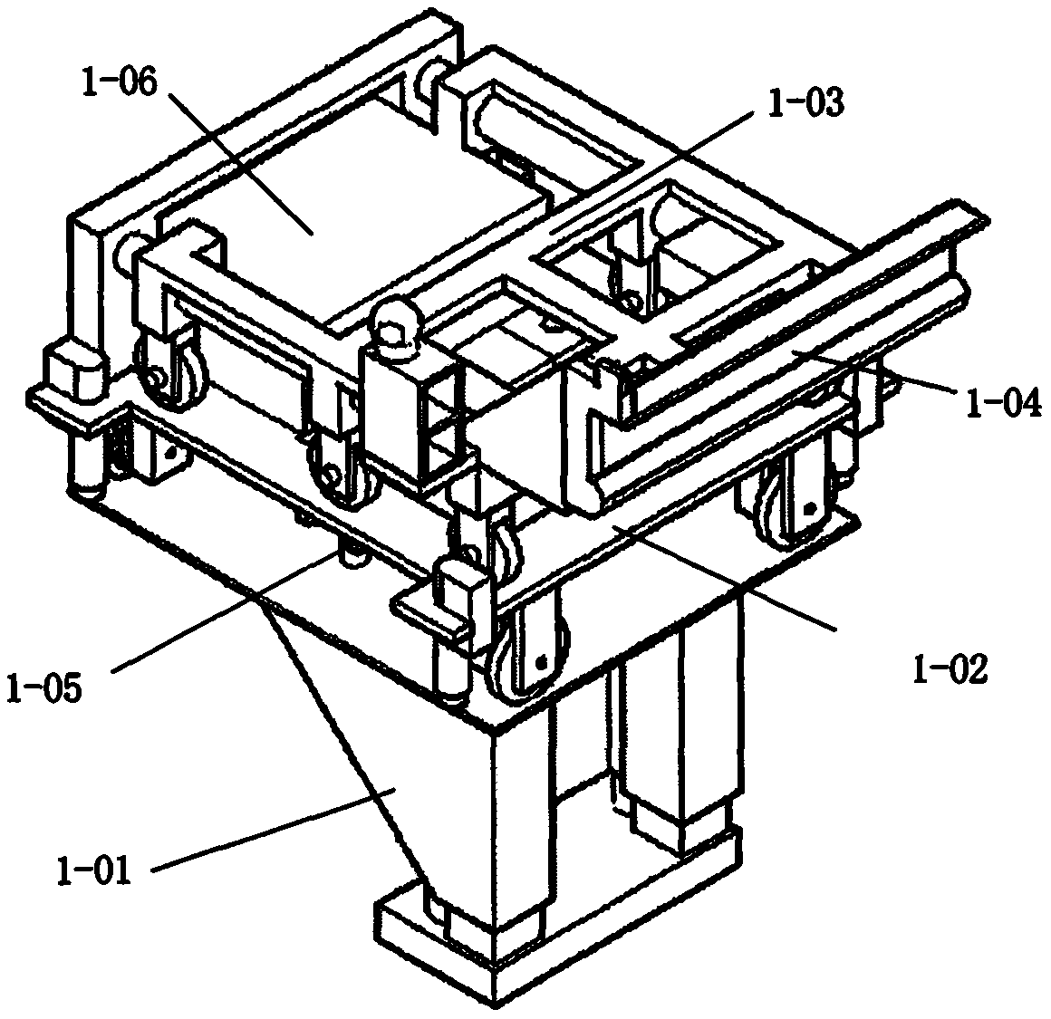
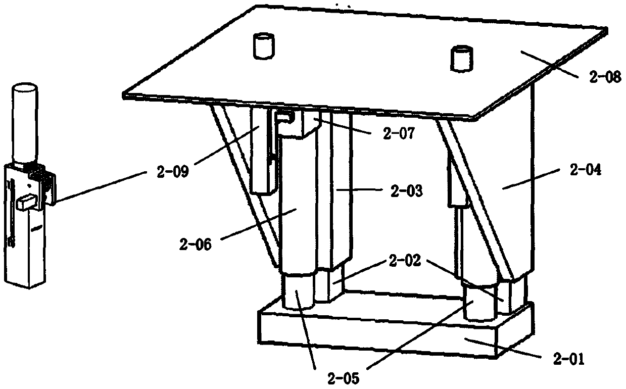
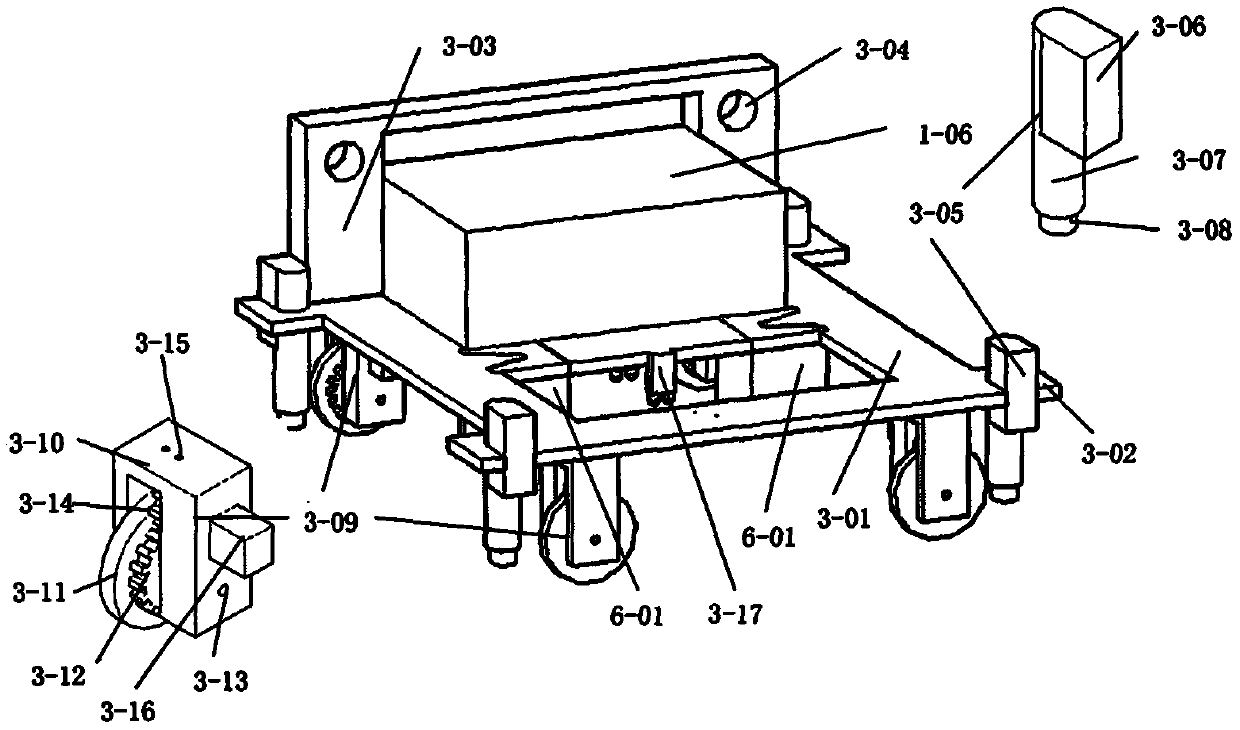
[0007] Aiming at the low efficiency of anti-slipping of trains in various railway yards, affecting the timeliness of vehicle turnover, and the problems of potential safety hazards, the invention discloses a technical device for automatically implementing anti-slipping of iron-shoe robots by controlling the supporting system of iron-shoe robots through artificial intelligence technology , the working principle of the iron shoe robot matching system of the present invention is mainly provided by the iron shoe walking control module to provide electric energy and coordinate and control the actions of the iron shoe walking lifter, iron shoe walking trolley, iron shoe flat push frame, and iron shoe walking lock. It can move from the iron shoe box under the foundation to the ground through the iron shoe lifting device, realize the interlocking and separation of the iron shoe driving lifter and the iron shoe driving car through the iron shoe walking lock, and use the iron shoe flat The push frame sends the iron shoe robot on the iron shoe loader to the rail, and finally the iron shoe returns to the iron shoe box on the original road

Method used


Image

  • Iron shoe robot matching system
  • Iron shoe robot matching system
  • Iron shoe robot matching system

Examples


Embodiment Construction

[0025] In order to enable those skilled in the art to better understand the technical solutions of the present invention, the present invention will be described in further detail below in conjunction with the accompanying drawings and specific embodiments. Hereinafter, embodiments of the present invention will be described in detail, examples of which are shown in the accompanying drawings, wherein the same or similar reference numerals denote the same or similar elements or elements having the same or similar functions throughout. The embodiments described below by referring to the figures are examples only for explaining the present invention and should not be construed as limiting the present invention. Those skilled in the art will understand that the singular forms "a", "an", "said" and "the" used herein may also include plural forms unless otherwise stated. It should be further understood that the word "comprising" used in the description of the present invention refers...


PUM


Abstract

The invention aims to solve the problem that low anti-slip efficiency of train sets in each yard of a railway influences the vehicle turnaround effectiveness and causes potential safety hazard problems; and discloses technical equipment for controlling an iron shoe robot supporting system to complete automatic anti-slip implementation of an iron shoe robot through an artificial intelligence technology. According to the working principle of the iron shoe robot supporting system, electric energy is mainly provided by the iron shoe walking vehicle control module, and coordinated control is conducted on actions of an iron shoe walking vehicle lifter, an iron shoe walking vehicle, an iron shoe horizontal pushing frame and an iron shoe walking lock; the iron shoe walking vehicle lifter can automatically move to the ground from the iron shoe box under the foundation through the iron shoe walking vehicle lifter, interlocking and separation of the iron shoe walking vehicle lifter and an iron shoe walking vehicle are achieved through the iron shoe walking lock, the iron shoe robot on an iron shoe loader is conveyed to a steel rail through an iron shoe horizontal pushing frame, and finally the iron shoe walking vehicle returns to the iron shoe box along the original path.

Description

technical field [0001] The invention relates to the innovation and design of a matching system for a railway iron shoe robot. Background technique [0002] Anti-slip braking of iron shoes has always been an important part of railway vehicle work. For a long time, the anti-slip technology of iron shoes has been implemented manually. During the anti-slip process, the staff need to lift heavy iron shoes from the iron shoe box , walk a long distance to the vicinity of the wheel set of the train that needs to be anti-slip, and then after joint control with the relevant driver or other train management personnel, climb onto the rail under the train and place the iron shoes on the rail surface And close to the wheel set of the vehicle, and then fasten the heavy chain connected to the iron shoes on the pedal of the vehicle, and the anti-slip operation will be considered as completed after the joint control report. This process is inefficient and wastes time, which in turn affects t...

Claims


Application Information

Patent Timeline
IPC IPC(8): B61H7/04
CPCB61H7/04
Inventor 万鑫兴
Owner 万鑫兴
Learn More