Wood formwork splicing device and wood formwork splicing method

A splicing device and wood formwork technology, which is applied to the joints of formwork/formwork/work frame, formwork/formwork components, and on-site preparation of building components, can solve problems affecting the quality of concrete pouring, cracking, etc., and achieve Improve flatness and sensory quality, easy to use, and prevent slurry leakage

Inactive Publication Date: 2020-08-18
CHINA FIRST METALLURGICAL GROUP
View PDF5 Cites 2 Cited by
  • Summary
  • Abstract
  • Description
  • Claims
  • Application Information

AI Technical Summary

Problems solved by technology

[0003] In view of this, the present invention proposes a wood formwork splicing device and a wood formwork splicing method, aiming to solve the problem that the existing

Method used


Image

  • Wood formwork splicing device and wood formwork splicing method
  • Wood formwork splicing device and wood formwork splicing method
  • Wood formwork splicing device and wood formwork splicing method

Examples


Embodiment Construction

[0031] Exemplary embodiments of the present disclosure will be described in more detail below with reference to the accompanying drawings. Although exemplary embodiments of the present disclosure are shown in the drawings, it should be understood that the present disclosure may be embodied in various forms and should not be limited by the embodiments set forth herein. Rather, these embodiments are provided for more thorough understanding of the present disclosure and to fully convey the scope of the present disclosure to those skilled in the art. It should be noted that, in the case of no conflict, the embodiments of the present invention and the features in the embodiments can be combined with each other. The present invention will be described in detail below with reference to the accompanying drawings and examples.

[0032] Device example:

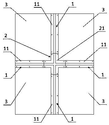
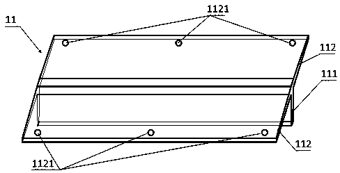
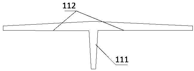
[0033] see figure 1 , Image 6 and Figure 9 , which shows the preferred structure of the wood formwork splicing device provided ...


PUM


Abstract

The invention provides a wood formwork splicing device and a wood formwork splicing method. The wood formwork splicing device comprises a splicing strip and a splicing head, wherein a splicing seam between any two adjacent wood formworks is connected through the splicing strip; the splicing positions of the at least three wood formworks are connected through the splicing head so that the wood formworks can be integrally spliced into a combined formwork structure. The flat and straight gaps are filled with the splicing strips in the splicing gaps of the two wood formworks, the splicing heads are adopted at the splicing positions of the wood formworks for lap joint, and then all splicing seams are connected into a whole, so that gaps generated by splicing of the wood formworks are effectively eradicated, and the flatness of the surfaces of the wood formworks is improved.

Description

technical field [0001] The invention relates to the technical field of civil engineering, in particular to a wood formwork splicing device and a wood formwork splicing method. Background technique [0002] In the construction site, because the wooden formwork can pour concrete at the same time, the concrete construction joints can be minimized, the wooden formwork is lighter in weight, which can reduce the bearing capacity of the entire layer of cast-in-place concrete, and the wooden formwork can be assembled and disassembled flexibly, and the construction performance is good According to the needs of the project, it can be cut into the required special specifications at will, which greatly improves the progress of the project. However, after many turnovers, improper use or unreasonable dismantling of the wooden formwork, the wooden formwork is prone to warping, cracking, missing corners and other problems. As a result, it is difficult to handle the joints in the subsequent ...

Claims


Application Information

Patent Timeline
IPC IPC(8): E04G9/02E04G9/04E04G17/00E04G17/02
CPCE04G9/02E04G9/04E04G17/00E04G17/02
Inventor 宋公文潘美雪任家乐林齐鸿林家鑫
Owner CHINA FIRST METALLURGICAL GROUP
Why Eureka
Try Eureka