Fuel injector flow measurement system and measurement method

A flow measurement and measurement system technology, which is applied in the fuel injector flow measurement system and measurement field, can solve the problems of low pressure control accuracy, high measurement cost, error in operation results, etc., so as to shorten the pressure build-up time, improve the measurement efficiency, reduce The effect of small temperature fluctuations

Active Publication Date: 2022-07-22
FAW JIEFANG AUTOMOTIVE CO
View PDF0 Cites 0 Cited by
  • Summary
  • Abstract
  • Description
  • Claims
  • Application Information

AI Technical Summary

Problems solved by technology

[0004] 1. The existing fuel injector flow measurement device usually uses an eddy current sensor to measure the online flow of the fuel injector. The measurement accuracy is low and cannot meet the measurement accuracy of ±0.5%, and the accuracy retention during the measurement process is poor ;
[0005] 2. The existing fuel injector flow measurement device has a slow measurement speed and cannot meet the measurement time requirement within 30 seconds;
[0006] 3. The existing fuel injector flow measurement device has a small range of use and a single function, and cannot flexibly configure process parameters;
[0007] 4. The existing fuel injector flow measurement device ignores the temperature difference problem of the fuel injector during actual use, and lacks the temperature compensation function, so that there is a large error between the measurement results and the operating results under actual working conditions;
[0008] 5. The existing fuel injector flow measurement device has low precision in controlling the pressure in the measurement circuit, which makes the pressure in the pipeline at the measurement end fluctuate greatly, which affects the measurement accuracy;
[0009] 6. The measuring circuit life of the existing fuel injector flow measuring device is relatively short, prone to sticking of components such as hydraulic valves, and the cost of measuring is relatively high

Method used


Image

  • Fuel injector flow measurement system and measurement method

Examples


specific Embodiment approach

[0069] In order to clearly and completely describe the technical solution of the present invention and its specific working process, with reference to the accompanying drawings, the specific embodiments of the present invention are as follows:

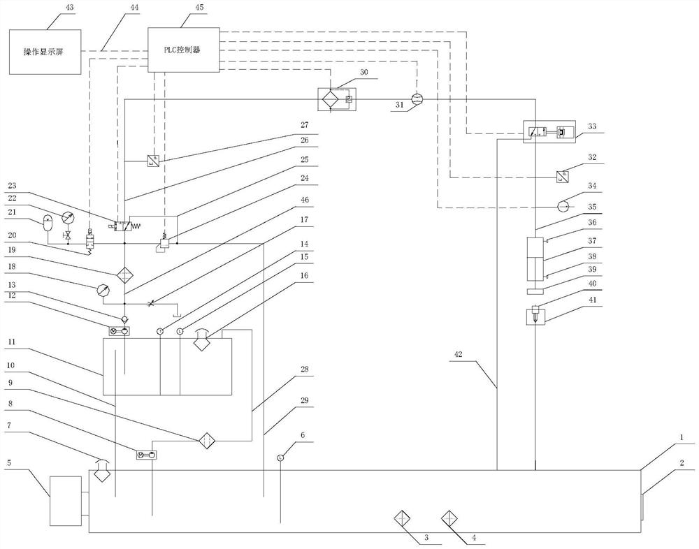
[0070] The invention discloses a fuel injection nozzle flow measurement system, such as figure 1 As shown in the figure, the measurement system adopts a double oil tank structure in which the filter oil tank 1 and the working oil tank 11 are connected in series. A voltage stabilizing component and a pneumatic pressure regulating valve 24 are installed in parallel between one side, and the other side of the reversing valve 11 at the outlet end is connected to the mass flow meter 31 and one side pipeline of the reversing valve 33 at the measuring end in turn through the working oil pipe 26 Connection, one oil outlet on the other side of the reversing valve 33 at the measuring end is connected to the pipeline of the measuring assembly thr...


PUM


Abstract

The invention discloses a fuel injection nozzle flow measurement system and a measurement method. The measurement system adopts a double fuel tank mechanism to realize the circulating filtration rate of the measured oil. A throttle valve is arranged at the outlet end of the fuel tank to control the fuel injection nozzle flow, and through Setting the start-up pressure regulating valve realizes rapid adjustment of the measured oil pressure in the measuring circuit, and absorbs the pressure fluctuations in the measuring circuit by setting the pressure stabilizing component. In addition, the dual oil tank mechanism is provided with a constant temperature control component to adjust the temperature in the oil tank; the measurement method realizes the input of control parameters to the PLC controller by operating the display screen, and according to the actual measurement of the oil temperature at the measuring end. The flow value measured by the meter is compensated. After the measurement is completed, the corresponding measurement process parameters are formed into a formula, which is convenient to call, change, download or delete. The invention realizes accurate and rapid measurement of the flow rate of the online fuel injector.

Description

technical field [0001] The invention belongs to the technical field of measuring components of a diesel engine fuel system, and in particular relates to a fuel injection nozzle flow measuring system and a measuring method. Background technique [0002] The fuel injector is a key component in the fuel system. The manufacturing level of the fuel injector directly affects the injection effect of the fuel system, thereby affecting various indicators of the engine. In the fuel system, especially in the diesel fuel system, the flow value of each component in the high-pressure hydraulic circuit and its corresponding relationship directly affect the engine performance. With the increasingly strict emission regulations, the electronically controlled high pressure common rail technology has been widely used, and the diesel engine fuel system has also developed in the direction of higher injection pressure and higher flow control accuracy. For this reason, the flow measurement of the ...

Claims


Application Information

Patent Timeline
Patent Type & Authority Patents(China)
IPC IPC(8): G01F1/86G01F15/00G01F15/12G01K13/02
CPCG01F1/86G01F15/005G01F15/125G01K13/02
Inventor 吴淳武吴欲龙周峰张宝田庞逸陆洋文勤王秀刚
Owner FAW JIEFANG AUTOMOTIVE CO
Why Eureka
Try Eureka