Device and method for monitoring water pressure outside shield tunnel
A monitoring device and water pressure technology, which is applied in the direction of measuring devices, measuring fluid pressure, tunnels, etc., can solve the problems of potential safety hazards, difficulties in water sealing, and easily damaged segment structures, etc., so as to facilitate later maintenance, installation, The effect of easy replacement
- Summary
- Abstract
- Description
- Claims
- Application Information
AI Technical Summary
Problems solved by technology
Method used
Image

Examples
Embodiment 1
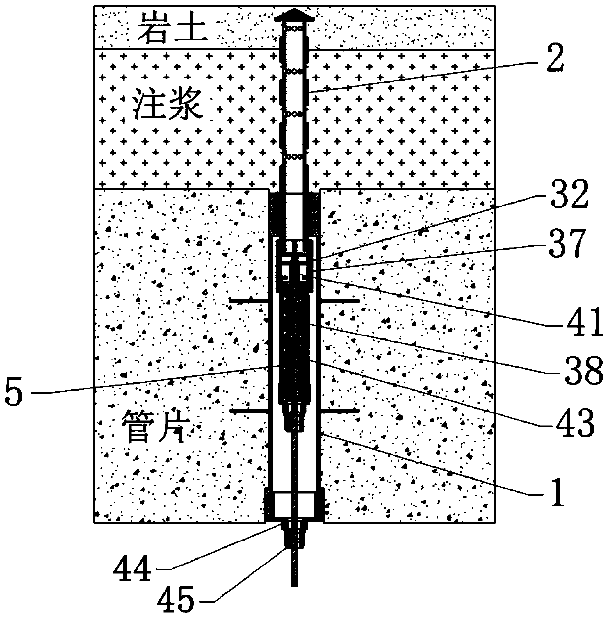
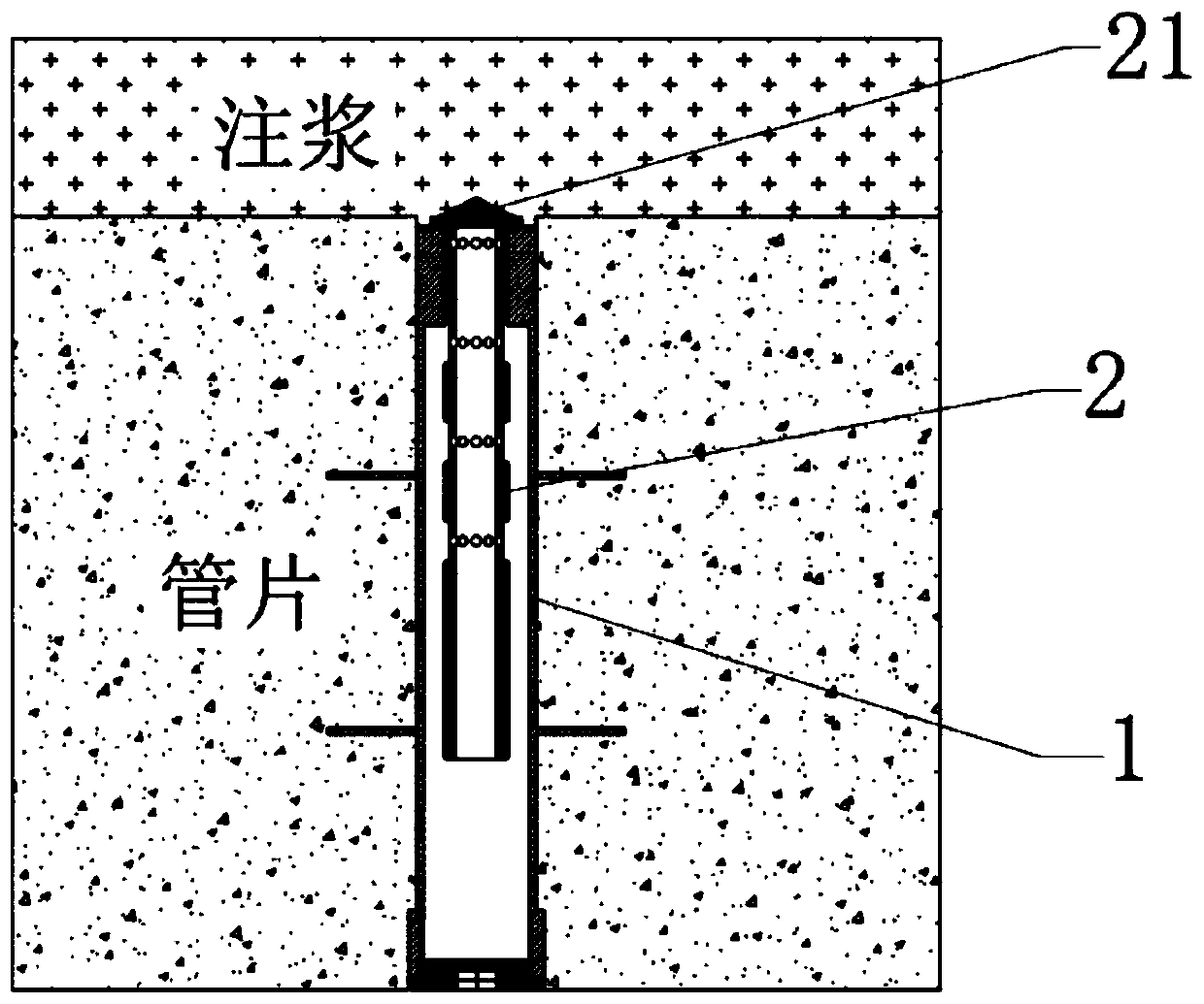
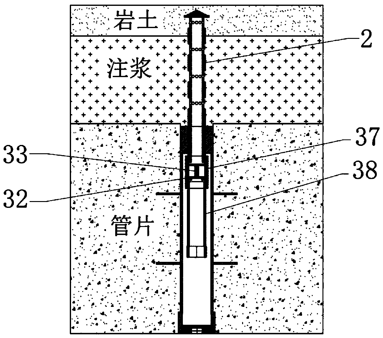
[0049] Water pressure monitoring device outside the shield tunnel, such as Figure 1~3 As shown, it includes a pre-embedded casing 1, a water inlet filter pipe 2, a water interception device 3, and a piezometer monitoring assembly 4. 3 is installed at the end of the water inlet filter pipe 2, and the piezometer monitoring component 4 is connected with the water interception device 3 and installed in the embedded casing 1.
[0050]When the water inlet filter pipe 2 penetrates the grouting layer, the water flow in the grouting layer flows into the water inlet filter pipe 2. Since the water quality has a high calcium content after the grouting, although the sensor is equipped with a permeable stone, the permeable stone can prevent stones from Silt and other substances block the sensor, but the water containing calcification is easy to adhere to the permeable stone, and the sensor will be blocked after a period of time, making the sensor invalid and unable to measure normally. Th...
Embodiment 2
[0065] A monitoring method of the water pressure monitoring device outside the shield tunnel provided by Embodiment 1, the monitoring method includes the following steps:
[0066] (1) The water inlet filter pipe passes through the grouting layer to reach the rock-soil layer, and the external water of the rock-soil layer enters the water inlet filter pipe;
[0067] (2) Screw the piezometer monitoring assembly into the outer sleeve from the inner arc surface (that is, the hole), so that the top valve part pushes the stop valve;
[0068] (3) The external water entering the water inlet filter pipe flows into the outer sleeve and the inner sleeve sequentially through the stop valve, and contacts the water pressure sensor, and the water pressure sensor measures the pressure of the external water.
Embodiment 3
[0070] An installation method of the water pressure monitoring device outside the shield tunnel provided by Embodiment 1, the installation method includes the following steps:
[0071] (1) Preparation work: prepare the embedded casing, ensure that the length of the embedded casing is about 5mm shorter than the thickness of the segment, and avoid that the embedded casing is longer than the template and cannot be placed in the segment formwork Install.
[0072] The purpose of pre-embedding is to allow the water inlet filter pipe to pass through the outer arc surface (ie, outside the tunnel), and to realize the installation of the water pressure sensor from the inner arc surface (ie, inside the tunnel).
[0073] Then perform the following steps:
[0074] (2) Before the segment is produced, the upper and lower ends of the pre-embedded casing are blocked with stainless steel protective caps, such as Figure 8 As shown, the plug can be used to prevent concrete or other sundries fr...
PUM
 Abstract
Description
Claims
Application Information
PatSnap Eureka turns technology decisions into work you can execute. Powered by our Innovation Knowledge Graph, it runs expert workflows across engineering, life sciences, materials and intellectual property. Get your review-ready output in minutes.


