Co-cavity spiral resonance filter

A helical resonator and helical resonance technology, which is applied in the field of filtering, can solve the problems of inability to transmit zero out-of-band suppression, etc.

Pending Publication Date: 2020-08-18
迈微思(深圳)科技有限公司
View PDF0 Cites 0 Cited by
  • Summary
  • Abstract
  • Description
  • Claims
  • Application Information

AI Technical Summary

Problems solved by technology

[0004] The main purpose of the present invention is to propose a resonant spiral resonator filter, which aims to solve the problem that the existing resonant spiral resonator filter cannot generate transmission zeros at specified frequency points, resulting in substandard out-of-band suppression

Method used


Image

  • Co-cavity spiral resonance filter
  • Co-cavity spiral resonance filter
  • Co-cavity spiral resonance filter

Examples


Embodiment Construction

[0029] The following will clearly and completely describe the technical solutions in the embodiments of the present invention with reference to the accompanying drawings in the embodiments of the present invention. Obviously, the described embodiments are only part of the embodiments of the present invention, not all of them. Based on the embodiments of the present invention, all other embodiments obtained by persons of ordinary skill in the art without creative efforts fall within the protection scope of the present invention.

[0030] It should be noted that if there is a directional indication (such as up, down, left, right, front, back...) in the embodiment of the present invention, the directional indication is only used to explain the position in a certain posture (as shown in the accompanying drawing). If the specific posture changes, the directional indication will also change accordingly.

[0031] In addition, if there are descriptions involving "first", "second" and ...


PUM


Abstract

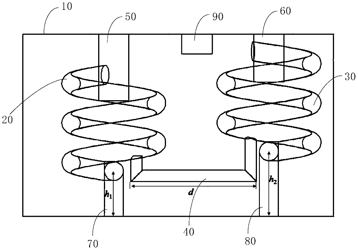
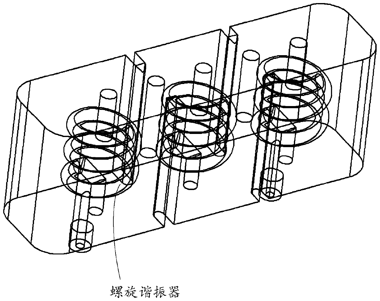
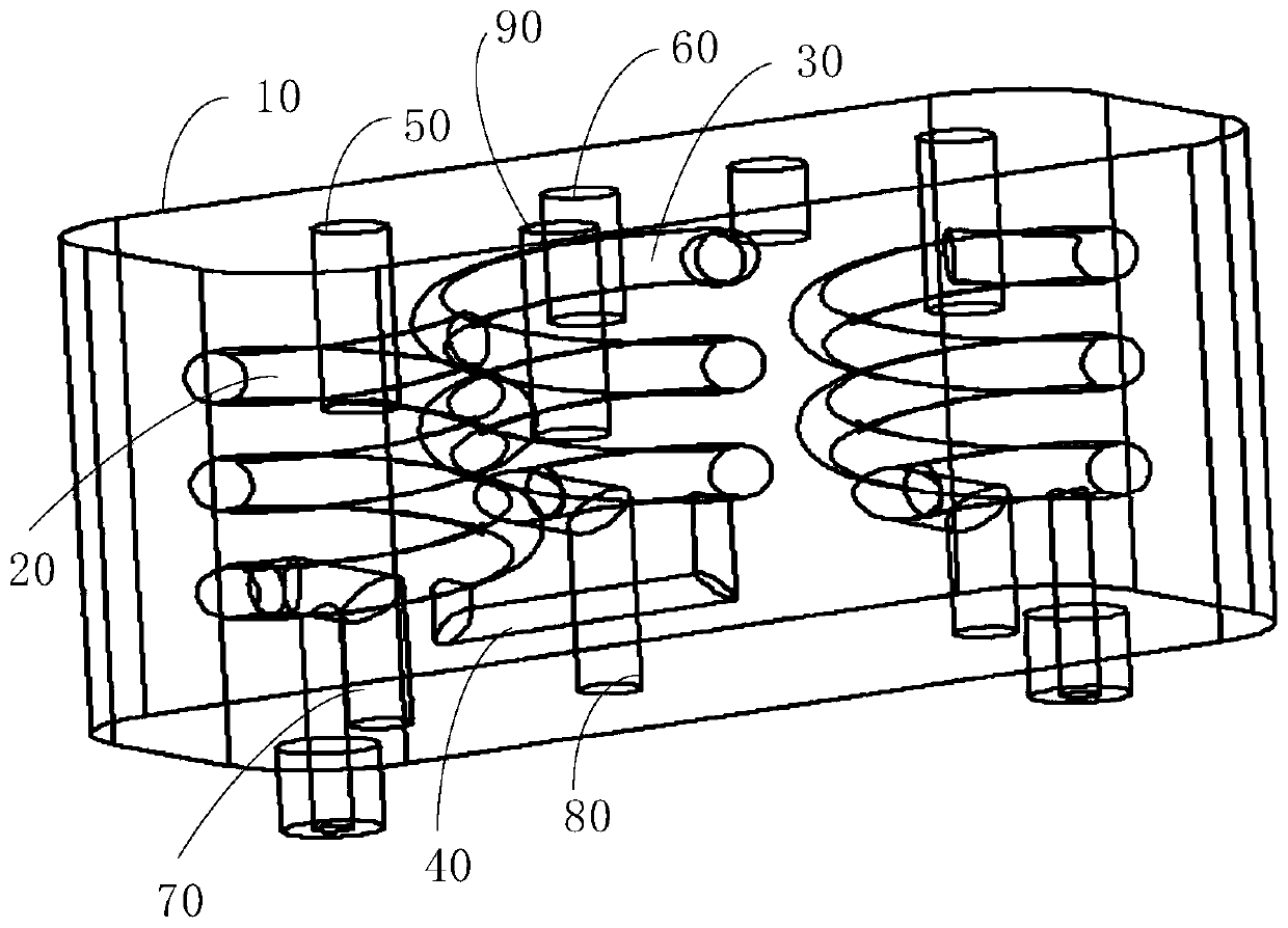
The invention discloses a common-cavity spiral resonance filter which comprises a first spiral resonator, a second spiral resonator, a first dispersion structure and a shell. The first spiral resonator is provided with a first end part and a second end part which are opposite to each other, and the second spiral resonator has a first end and a second end opposite to each other. A first dispersionstructure is connected between a first end of the first spiral resonator and a first end of the second spiral resonator, a cavity is formed in the shell, and the first spiral resonator, the second spiral resonator and the first dispersion structure are contained in the cavity. The technical scheme is used for solving the problem that the out-of-band rejection does not reach the standard due to thefact that an existing common-cavity spiral resonator filter cannot generate a transmission zero point.

Description

technical field [0001] The invention relates to the field of filter technology, in particular to a common cavity spiral resonator filter. Background technique [0002] The fifth-generation wireless communication network (5G) has gradually begun to be commercially deployed. In order to further improve the throughput of the wireless network, the base station of the 5G network adopts multiple-input multiple-output antenna technology (MIMO) and beam-forming (beam-forming) and other technologies. . Driven by these technologies, filters, one of the essential microwave components in wireless communications, will increase significantly with the advent of the 5G era. At the same time, the adoption of new technologies also puts forward stricter technical requirements for the miniaturization and performance of filters. [0003] At present, metal cavity filters widely used in base stations use a relatively independent cavity structure for each resonator. In order to improve the qualit...

Claims


Application Information

Patent Timeline
Patent Type & Authority Applications(China)
IPC IPC(8): H01P1/208
CPCH01P1/208
Inventor 孟幻韦大成
Owner 迈微思(深圳)科技有限公司
Why Eureka
Try Eureka