Predictive direct power control method

A power control and direct technology, applied in the output power conversion device, the conversion of AC power input to DC power output, electrical components, etc., can solve the problem of large static power difference, poor actual control effect, and harmonic content of grid-side input current. Large and other problems, to achieve the effect of good dynamic and static performance and good steady-state effect

Inactive Publication Date: 2020-08-18
XI AN JIAOTONG UNIV
View PDF7 Cites 0 Cited by
  • Summary
  • Abstract
  • Description
  • Claims
  • Application Information

AI Technical Summary

Problems solved by technology

[0005] Based on the existing model prediction, direct power control has the problem of large static power difference in steady state, which leads to poor actual control effect in steady state, large harmonic content of grid-side input current, and low system power factor. This application Provides a predictive direct power control method

Method used


Image

  • Predictive direct power control method
  • Predictive direct power control method
  • Predictive direct power control method

Examples


Embodiment Construction

[0036] Hereinafter, specific embodiments of the present application will be described in detail with reference to the accompanying drawings. According to these detailed descriptions, those skilled in the art can clearly understand the present application and can implement the present application. Without departing from the principles of the present application, the features in different embodiments can be combined to obtain new implementations, or some features in certain embodiments can be replaced to obtain other preferred implementations.

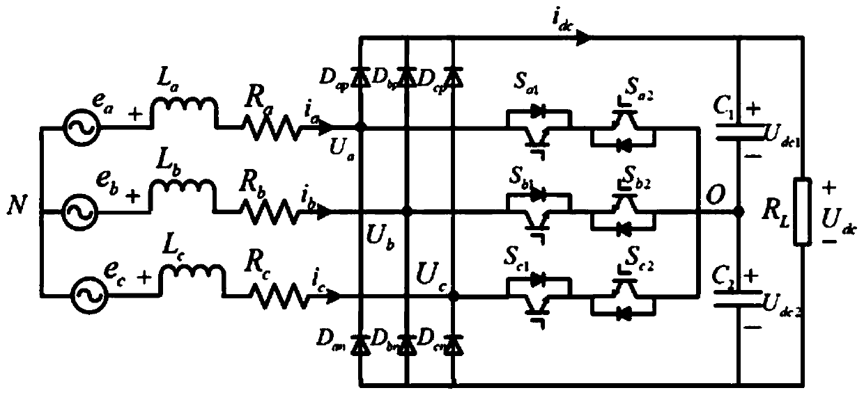
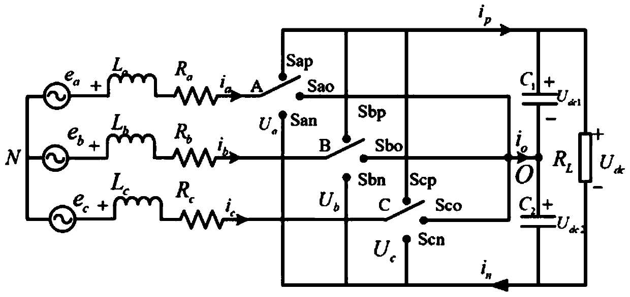
[0037] refer to Figure 1~4 , the present application provides a predictive direct power control method, the method comprising the following steps:

[0038] Step 1): set up the mathematical model of the rectifier in the two-phase stationary coordinate system, obtain the instantaneous active power and the instantaneous reactive power of the rectifier in the two-phase stationary coordinate system;

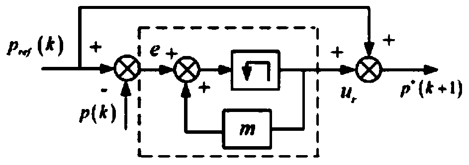
[0039] Step 2): design the index functi...


PUM


Abstract

The invention belongs to the technical field of rectifier control, and particularly relates to a predictive direct power control method. Common current control bits are based on voltage directional current control of feedforward decoupling, PARK conversion and PLL calculation need to be carried out, calculation is complex, and parameters of a PI controller are difficult to set and are greatly influenced by system parameters. The invention provides the predictive direct power control method, which comprises the steps of establishing a mathematical model of a rectifier in a two-phase static coordinate system, and obtaining instantaneous active power and instantaneous reactive power of the rectifier in the two-phase static coordinate system; designing an index function by taking the minimum error of the instantaneous active power and the instantaneous reactive power as a principle, and deriving a rectifier reference voltage vector calculation formula by taking a power grid voltage vectoras a basic control vector; adopting space vector modulation to realize fixed switching frequency control; and meanwhile, correcting the instantaneous active power and the instantaneous reactive powerby adopting internal model control. The output waveform quality in a steady state is improved.

Description

technical field [0001] The present application belongs to the technical field of rectifier control, and in particular relates to a predictive direct power control method. Background technique [0002] VIENNA rectifier, as a three-level PWM (pulse width modulation, PWM) rectifier, has the advantages of high power density, low device stress, and less input current harmonic content compared with the traditional two-point level PWM rectifier. Compared with the traditional diode clamp Bit type, flying capacitor clamp type three-level rectifier, its topology is simpler, less power devices are required, and there is no risk of bridge arm shoot-through without setting dead time. Therefore, in some high-power, high-density applications, VIENNA rectifier is a very ideal topology. Therefore, in recent years, it has been widely used in electric vehicle charging stations and charging pile systems, aerospace power supplies, etc. With the diversification of VIENNA rectifier applications,...

Claims


Application Information

Patent Timeline
Patent Type & Authority Applications(China)
IPC IPC(8): H02M7/217H02M1/08
CPCH02M1/08H02M7/2173H02M1/0025
Inventor 孟文新张杭张爱民孙丰瑞
Owner XI AN JIAOTONG UNIV
Why Eureka
Try Eureka