Digital signal time jitter measurement method and system

A digital signal and time jitter technology, applied in digital transmission systems, transmission systems, data exchange networks, etc., can solve the problems of slow measurement speed, high cost of oscilloscope, huge data and resource consumption, etc., to achieve wide adaptability and reduce difficulty and cost effects

Active Publication Date: 2020-08-18
UNIV OF ELECTRONICS SCI & TECH OF CHINA
View PDF10 Cites 2 Cited by
  • Summary
  • Abstract
  • Description
  • Claims
  • Application Information

AI Technical Summary

Problems solved by technology

[0005] Both of the above two commonly used methods have the advantage of being convenient and easy to implement, but both have the following disadvantages: 1. Manual access to a broadband spectrum analyzer or a high-sampling oscilloscope and its software is required, and online real-time measurement of jitter cannot be realized ; 2. The cost of broadband spectrum analyzer or oscilloscope with high sampling rate is relatively high; 3. The data and resource consumption of the above method is relatively large, and the measurement speed is relatively slow

Method used


Image

  • Digital signal time jitter measurement method and system
  • Digital signal time jitter measurement method and system

Examples


Embodiment

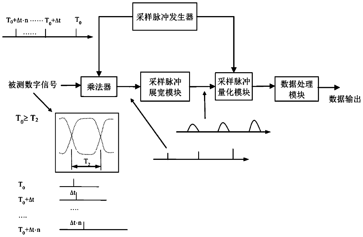
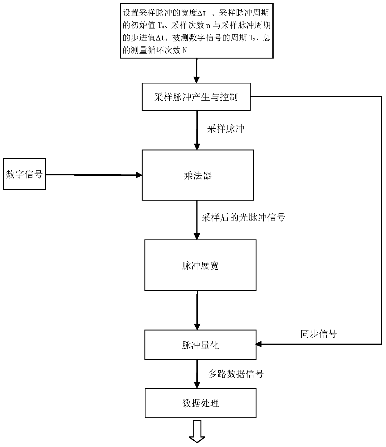
[0034] Sampling pulse generation and control: A period of T is generated by the sampling pulse generator 1, and a sampling pulse with an adjustable period and a pulse width of Δτ, where T 1 =T 0 +Δt n,T 0 As the initial value, set T 0 =10ns, n=(1,2,…..n) is a positive integer, indicating the number of sampling times, and the width of the sampling pulse Δτ is much smaller than the period T of the measured digital signal 2 , and T 2 =Δt·n. The measured digital signal has a period of T 2 The rate of =1ns is a pseudo-random code (non-return-to-zero code) of 1Gb / s, and n is set to 10; the width of the sampling pulse is Δτ=0.05ns; the step value of the sampling pulse period Δt=0.1ns; meet the preset conditions : T 0 ≥T 2 , Δτ≤Δt, n≥3.

[0035] When sampling for the first time, n=0, T 1 =T 0 =10ns, the sampling pulse and the measured digital signal are multiplied in the multiplier to complete the sampling, and then the pulse obtained after sampling is stretched by 10 times...


PUM


Abstract

The invention relates to a digital signal time jitter measurement method and system, and the method comprises the steps: A, completing the first sampling in one period of a measured digital signal through a sampling pulse with an adjustable period, and enabling the width of the sampling pulse to be smaller than one period of the measured digital signal; B, broadening and quantifying the sampled pulse, and recording the parameters of the current sampling; C, repeatedly sampling in one period of the measured digital signal, sequentially increasing the stepping values of the sampling pulse periods with the times corresponding to the sampling times to the periods of the sampling pulses during each subsequent sampling, and repeating the step B after each sampling until the predetermined times of sampling in one period of the measured digital signal is completed; and D, performing numerical calculation of time jitter according to all the sampling parameters to obtain a result of time jitterof the digital signal. According to the method, a measurement system can be modularized, online measurement can be realized, and the difficulty and the cost for quantifying the sampling pulse amplitude are effectively reduced.

Description

technical field [0001] The invention relates to a method for measuring time jitter in the field of digital signals, in particular to a method and system for measuring time jitter of periodic digital signals. Background technique [0002] In digital communication systems, the technical indicators of periodic digital signal time jitter will directly affect the performance of the transmission system, such as bit error rate, codec performance, etc. With the development of high-performance digital communication technology, accurate measurement of digital signal time jitter is required in practical applications to ensure the normal operation of the system. At present, the commonly used measurement methods of digital signal time jitter mainly include frequency domain spectrum measurement and analysis method and time domain high-speed sampling and calculation. [0003] Among them, the spectrum measurement and spectrum analysis method is to measure the power spectral density of the ...

Claims


Application Information

Patent Timeline
Patent Type & Authority Applications(China)
IPC IPC(8): H04L12/26
CPCH04L43/087
Inventor 邱琪夏琳莎黄涛苏君
Owner UNIV OF ELECTRONICS SCI & TECH OF CHINA
Why Eureka
Try Eureka