Eureka AIR delivers breakthrough ideas for toughest innovation challenges, trusted by R&D personnel around the world.

Novel roller straightener transmission assembly and transmission method thereof

A technology of roller leveler and transmission components, applied in the direction of electric components, electromechanical devices, electrical components, etc., can solve the problems of transmission components without emergency braking components, transmission components without protective measures, threats to the personal safety of staff, etc. Achieve the effects of avoiding damage to the universal coupling, low cost of assembly, and simple structure

Pending Publication Date: 2020-08-21
CHINA NAT HEAVY MACHINERY RES INSTCO
View PDF0 Cites 0 Cited by
  • Summary
  • Abstract
  • Description
  • Claims
  • Application Information

AI Technical Summary

Problems solved by technology

[0003] The purpose of the present invention is to overcome the deficiencies of the above-mentioned prior art, and provide a novel roller leveler transmission assembly and transmission method, which overcomes 1 in the prior art: when the strip steel drags the straightening roller to rotate at a high speed, it is connected to it. The universal coupling also follows its high-speed rotation, which makes the universal coupling extremely vulnerable and poses a major safety hazard; 2: The existing transmission components have no protective measures, which poses a threat to the personal safety of the staff; 3 : The existing transmission components do not have emergency braking components, and in an emergency, there are no other braking ways to choose from except power failure.

Method used


Image

  • Novel roller straightener transmission assembly and transmission method thereof
  • Novel roller straightener transmission assembly and transmission method thereof
  • Novel roller straightener transmission assembly and transmission method thereof

Examples


specific Embodiment approach

[0025] It should be noted that the structures, proportions, sizes, etc. shown in this specification are only used to cooperate with the content disclosed in the specification for the understanding and reading of those familiar with this technology, and are not used to limit the conditions for the implementation of the present invention , any modification of structure, change of proportional relationship or adjustment of size shall still fall within the scope covered by the technical content disclosed in the present invention without affecting the effect and purpose of the present invention. .

[0026] At the same time, terms such as "upper", "lower", "left", "right", "middle" and "one" quoted in this specification are only for the convenience of description and are not used to limit this specification. The practicable scope of the invention and the change or adjustment of its relative relationship shall also be regarded as the practicable scope of the present invention without...

Embodiment 1

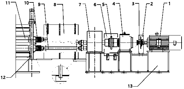
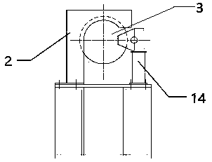
[0028] Such as Figure 1~2 As shown, the present invention discloses a novel roller straightening machine transmission assembly, including a motor 1, a brake disc coupling 3, a reducer 4, a drum gear coupling 5, a gear distribution box 7, a universal joint Shaft 9, overrunning clutch 10 and straightening roller 11, wherein motor 1, brake disc coupling 3, speed reducer 4, drum gear coupling 5 and gear distribution box 7 are connected coaxially in sequence, and the gear distribution The output end of the box 7 is connected to the input end of the universal coupling 9, wherein the output end of the universal coupling 9 is connected to the outer ring of the overrunning clutch 10, and the inner ring of the overrunning clutch 10 is connected to the straightening roller 11.

Embodiment 2

[0030] Such as Figure 1~2 As shown, the present invention discloses a novel roller straightening machine transmission assembly, including a motor 1, a brake disc coupling 3, a reducer 4, a drum gear coupling 5, a gear distribution box 7, a universal joint Shaft 9, overrunning clutch 10 and straightening roller 11, wherein motor 1, brake disc coupling 3, speed reducer 4, drum gear coupling 5 and gear distribution box 7 are connected coaxially in sequence, and the gear distribution The output end of the box 7 is connected to the input end of the universal coupling 9, wherein the output end of the universal coupling 9 is connected to the outer ring of the overrunning clutch 10, and the inner ring of the overrunning clutch 10 is connected to the straightening roller 11.

[0031] preferred, such as Figure 1~2 As shown, the motor 1, the brake disc coupling 3, the reducer 4, the drum gear coupling 5 and the gear distribution box 7 are respectively fixed on the upper end surface of...


PUM


Abstract

The invention discloses a novel roller straightener transmission assembly and a transmission method thereof. The novel roller straightener transmission assembly comprises a motor (1), a brake disc coupler (3), a speed reducer (4), a crowned tooth coupler (5), a gear distribution box (7), a universal coupler (9), an overrunning clutch (10) and a straightening roller (11), wherein the motor (1), thebrake disc coupler (3), the speed reducer (4), the crowned tooth coupler (5) and the gear distribution box (7) are sequentially and coaxially connected, the output end of the gear distribution box (7) is connected with the input end of the universal coupler (9), the output end of the universal coupler (9) is connected with the outer ring of the overrunning clutch (10), and the inner ring of the overrunning clutch (10) is connected with the straightening roller (11).

Description

technical field [0001] The invention belongs to the technical field of transmission of straightening rollers of straightening machines, and in particular relates to 3-roll, 5-roll, 7-roll or 9-roll leveling used in the uncoiling section of a cold rolling plant in the iron and steel field, a galvanizing unit or other similar units. The invention relates to a straightening roller transmission technology of a straightening machine, in particular to a novel transmission assembly and a transmission method of a roller straightening machine. Background technique [0002] In the iron and steel field, a roll leveler (3-roll, 5-roll, 7-roll or 9-roll form) is usually set up in the uncoiling section of the continuous rolling unit, galvanizing unit or other similar units for straightening the raw material The head of the strip or continuous straightening of the strip to improve the shape of the raw material. Under the existing technical conditions, the straightening roller actively dra...

Claims


Application Information

Patent Timeline
Patent Type & Authority Applications(China)
IPC IPC(8): B21D1/02B21D55/00H02K7/10
CPCB21D1/02B21D55/00H02K7/10
Inventor 姚养库张康武孙亚波
Owner CHINA NAT HEAVY MACHINERY RES INSTCO
Why Eureka
Eureka Blog
Learn More