
Unmanned aerial vehicle body temperature measuring device and method for smart city

A technology for measuring device and body temperature, which is applied in the direction of measuring device, radiation pyrometry, measuring heat, etc. It can solve the problems of fan damage, difficult operation, and inability to carry, so as to improve the service life, reduce the occupied space, and improve the structure. simple effect

Active Publication Date: 2020-08-21
鑫亿智慧科技有限公司
View PDF6 Cites 0 Cited by
  • Summary
  • Abstract
  • Description
  • Claims
  • Application Information

AI Technical Summary

Problems solved by technology

[0002] In recent years, due to the occurrence of some large-scale infectious diseases, some non-contact body temperature measurement equipment has been widely used. Therefore, there are certain requirements for UAV body temperature measurement devices in the market; but the existing unmanned The body temperature measurement device has a complex structure and is difficult to operate. Most drones cannot be folded or stretched, and are not easy to carry. Most drone fans are not equipped with protective devices, which can easily damage the fan and hurt the crowd, and most of them are unmanned. The machine has no buffer device, which reduces the service life of the drone and affects the use

Method used


Image

  • Unmanned aerial vehicle body temperature measuring device and method for smart city
  • Unmanned aerial vehicle body temperature measuring device and method for smart city
  • Unmanned aerial vehicle body temperature measuring device and method for smart city

Examples


Embodiment Construction

[0028] The following will clearly and completely describe the technical solutions in the embodiments of the present invention with reference to the accompanying drawings in the embodiments of the present invention. Obviously, the described embodiments are only some, not all, embodiments of the present invention. Based on the embodiments of the present invention, all other embodiments obtained by persons of ordinary skill in the art without making creative efforts belong to the protection scope of the present invention.

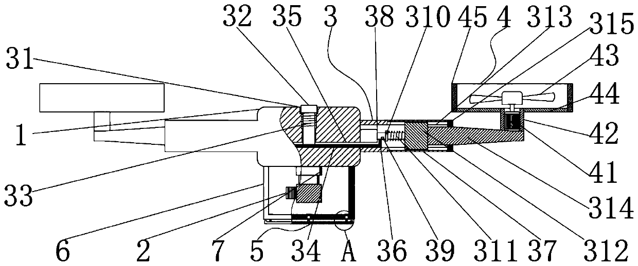
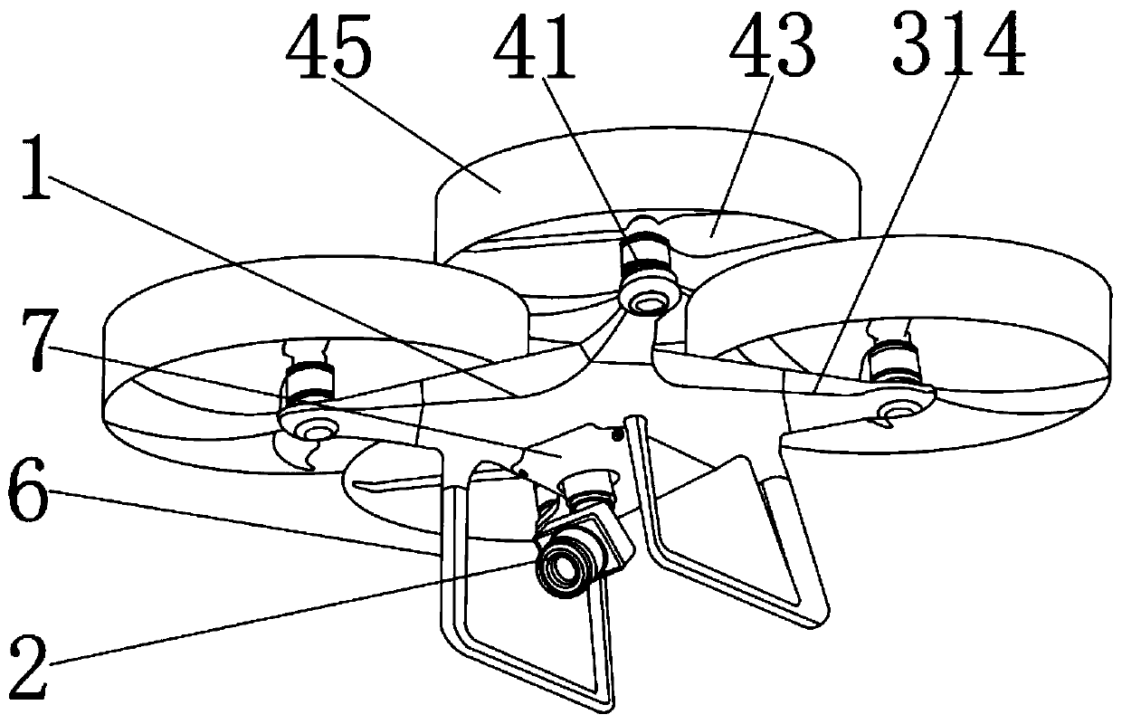
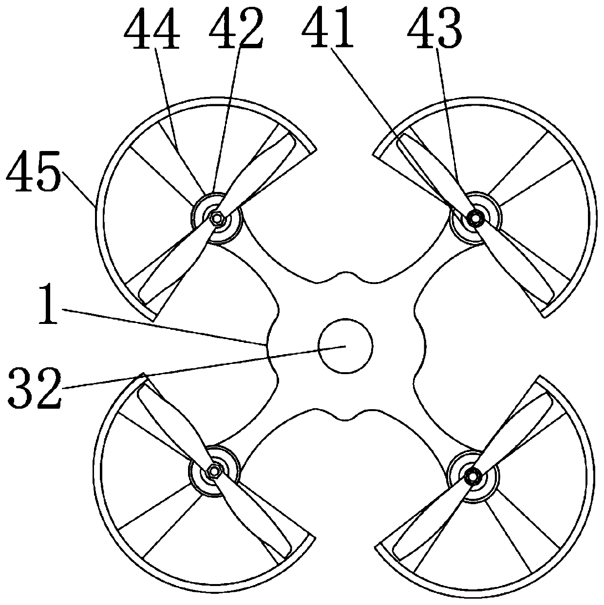
[0029] see Figure 1-5, the present invention provides a technical solution: a drone body temperature measurement device for a smart city, including a drone body 1, a temperature detector body 2, a telescopic component 3, a protection component 4, a buffer component 5, a support leg 6 and a temperature measurement The device body mounting seat 7, the temperature detector body 2 is installed on the bottom outer wall of the drone body 1, and the temperature dete...


PUM


Abstract

The invention discloses an unmanned aerial vehicle body temperature measurement device and method for a smart city. The device comprises an unmanned aerial vehicle main body, a temperature detector body, a telescoping assembly, a protection assembly, a buffering assembly, supporting legs, and a temperature detector body installation seat. The outer wall of the bottom end of the unmanned aerial vehicle main body is provided with the temperature detector body. The telescopic assembly, the protection assembly and the buffering assembly are adopted, a first sliding block, a second connecting rod,a first telescopic rod, a limiting baffle, a second spring, a second sliding block and a third connecting rod in the telescopic assembly are matched, so that the unmanned aerial vehicle has a telescopic function; the device is simple in structure and convenient to operate, and the occupied space of the unmanned aerial vehicle is reduced; a second sleeve, a fan, a connecting plate and a third sleeve in the protection assembly are matched, so that the unmanned aerial vehicle has a protection function; and through cooperation of a second telescopic rod, a third spring and a buffer baffle in the buffer assembly, the unmanned aerial vehicle has a buffer protection function, the unmanned aerial vehicle is further protected, and the service life of the unmanned aerial vehicle is prolonged.

Description

technical field [0001] The invention relates to the technical field of unmanned aerial vehicle equipment, in particular to an unmanned aerial vehicle body temperature measuring device and method for a smart city. Background technique [0002] In recent years, due to the occurrence of some large-scale infectious diseases, some non-contact body temperature measurement equipment has been widely used. Therefore, there are certain requirements for UAV body temperature measurement devices in the market; but the existing unmanned The body temperature measurement device has a complex structure and is difficult to operate. Most drones cannot be folded or stretched, and are not easy to carry. Most drone fans are not equipped with protective devices, which can easily damage the fan and hurt the crowd, and most of them are unmanned. The drone does not have a buffer device, which reduces the service life of the drone and affects its use. Contents of the invention [0003] The object o...

Claims


Application Information

Patent Timeline
IPC IPC(8): B64C39/02B64C27/08B64C1/06B64C1/30B64C27/00B64C25/62G01K13/00G01J5/00A61B5/01
CPCB64C39/024B64C27/08B64C1/06B64C1/30B64C27/006B64C25/62G01K13/00G01J5/00A61B5/01B64U2101/00
Inventor 张春喜郭琼辉
Owner 鑫亿智慧科技有限公司
Learn More