Double-limb pier bent cap

A technology for pier capping beams and capping beams, which is applied to bridges, bridge parts, bridge materials, etc., can solve the problems of poor overall bridge landscape effect, increase, and design difficulty, etc. Excellent force performance

Pending Publication Date: 2020-08-21
JSTI GRP CO LTD
View PDF0 Cites 1 Cited by
  • Summary
  • Abstract
  • Description
  • Claims
  • Application Information

AI Technical Summary

Problems solved by technology

[0003] In the case of traditional single-column pier cap beams, in order to provide greater lateral rigidity and strength for the structure when the vertical dimension of the column is limited, the cross-sectional dimension along the bridge direction is often larger, and increasing the cross-sectional dimension also improves The bending stiffness along the bridge direction of the structure further increases the internal force of the structure, and it is often necessary to find a balance between the two, which is difficult to design, especially when the column height is small, which is not conducive to the bridge's resistance to the bridge along the bridge. Directional temperature force, vehicle braking force and strong earthquake force
When the span of the bridge is small, such thick piers reduce the permeability of the driving vision under the bridge, and the overall landscape effect of the bridge is poor

Method used


Image

  • Double-limb pier bent cap
  • Double-limb pier bent cap
  • Double-limb pier bent cap

Examples


Embodiment 1

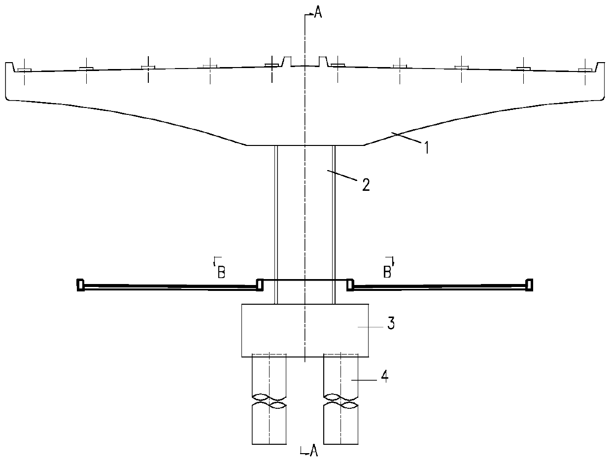
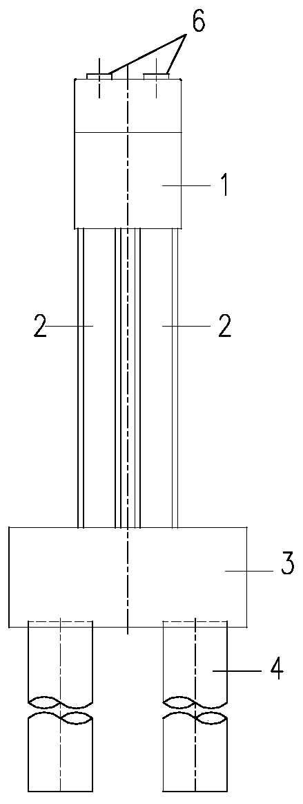
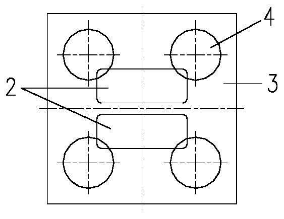
[0044] combine Figure 1 ~ Figure 3 , this embodiment mainly describes a viaduct pier cover beam arranged in the middle zone of the ground road, including a cover beam 1 supporting the upper structure, and two longitudinally separated columns 2 are arranged at the bottom of the cover beam 1, and the columns 2 are completely Arranged in the middle zone, while the column 2 is placed on the cap 3, and four pile foundations 4 are set under the cap 3.

[0045] The specific implementation process is as follows:

[0046] 1. Utilize the middle zone of the existing ground road, design and construct cap 3 and foundation 4 according to conventional methods; according to the geological conditions under the bridge, cap 3 is buried 1.0-1.5 meters below the ground.

[0047] 2. Determine the transverse width of the column 2 according to the width of the middle section, and calculate the longitudinal width and column spacing of the column 2 in combination with the specific stress conditions, ...

Embodiment 2

[0051] combine Figure 4 ~ Figure 6 , this embodiment mainly describes a viaduct bridge pier cover beam with transverse tie beams. Compared with Example 1, the difference between this embodiment is that two longitudinal columns 2 are connected by transverse tie beams 5 to improve the overall stability of the structure. , suitable for high bridge piers. The transverse tie beam 5 is generally arranged in the middle of the column 2. When there are multiple high piers arranged, considering the aesthetic requirements under the bridge, it is advisable to place the transverse tie beam 5 at the same height.

[0052] It should be noted that the section of the column in the embodiment is not limited to a rounded rectangle. When the pier height is high, the column of the double-leg pier cover beam can also be made in the direction of the bridge or the direction of the bridge according to the force requirements. Variable section form.


PUM


Abstract

The invention relates to a double-limb pier bent cap which comprises a bent cap body. Two longitudinally separated stand columns are arranged at the bottom of the bent cap and arranged on a bearing platform, and a foundation is arranged below the bearing platform. The bent cap can be of a common reinforced concrete structure or a prestressed concrete structure. The stand columns have reinforced concrete solid structures, the side length of the cross section of each stand column in the transverse direction of the bridge is larger than that of the cross section in the longitudinal direction of the bridge, the stand columns are divided into two independent stand columns in the longitudinal direction of the bridge to form double-limb piers, and the centers of the two stand columns correspond to the upper structure supports in position. The double-limb piers and a group of pile foundations composed of cast-in-situ bored piles are in structural transition through the bearing platform, and the two ends of the double-limb piers should be fixedly connected with the bent cap and the bearing platform respectively. The anti-bending rigidity of the structure in the bridge direction can be greatly reduced, the structural anti-seismic property objective is achieved, the construction cost is saved, the under-bridge driving view is enlarged, and the structure is safe, reliable, economical and attractive.

Description

technical field [0001] The invention belongs to the technical field of bridge engineering, and in particular relates to a double-leg pier cap beam. Background technique [0002] With the rapid development of urban traffic construction, it is inevitable in the design of urban viaducts to use the central divider of the ground road system to arrange piers. The two columns of the bridge are supported under the cover beam, the top of the column is consolidated with the cover beam, and the transition between the column and the pile foundation is through the cap. When the layout space of the pier is further restricted, the lateral distance between the two columns gradually decreases and evolves into Cap-beam form for single-column piers. [0003] In the case of traditional single-column pier cap beams, in order to provide greater lateral rigidity and strength for the structure when the vertical dimension of the column is limited, the cross-sectional dimension along the bridge dire...

Claims


Application Information

Patent Timeline
Patent Type & Authority Applications(China)
IPC IPC(8): E01D19/02E02D27/14E02D27/42E01D101/26E01D101/28
CPCE01D19/02E01D2101/26E01D2101/28E02D27/14E02D27/42
Inventor 郭红雨
Owner JSTI GRP CO LTD
Why Eureka
Try Eureka