
Construction method of pouring concrete beams layer by layer on soft ground

A technology of concrete beams and soft soil foundations, applied in buildings, bridges, bridge construction, etc., can solve the problems of reducing the strength and stability of buildings, affecting the safety and durability of concrete, and reducing the service life of structures. The effect of uniform settlement of cores, improvement of foundation stability, and reduction of the probability of cracks

Active Publication Date: 2022-02-08
GUANGXI TRANSPORTATION SCI & TECH GRP CO LTD +1
View PDF6 Cites 0 Cited by
  • Summary
  • Abstract
  • Description
  • Claims
  • Application Information

AI Technical Summary

Problems solved by technology

For cast-in-place brackets, especially for concrete beams that are supported by full brackets and cast in layers, there are many reasons such as poor shrinkage of layered concrete, settlement of brackets, concrete hydration temperature drop, construction technology, etc. Cracks in the concrete will accelerate the carbonation of the concrete and reduce the corrosion resistance of the structure, and eventually reduce the strength and stability of the bridge structure and buildings, thereby reducing the service life of the structure and seriously affecting the safety and durability of the concrete. sex
However, for concrete beams cast in layers on soft foundations, there are often concrete cracks caused by excessive stress in the early pouring beams, causing safety and durability problems. Soft soil foundations mainly refer to deposits in still water or slow flowing water It is a kind of saturated cohesive soil in soft plastic to flow plastic state, which has high natural water content, high compressibility, low bearing capacity and poor water permeability.

Method used


Image

  • Construction method of pouring concrete beams layer by layer on soft ground
  • Construction method of pouring concrete beams layer by layer on soft ground
  • Construction method of pouring concrete beams layer by layer on soft ground

Examples


Embodiment

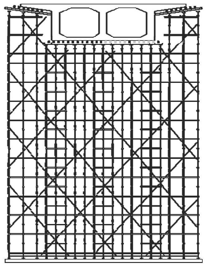
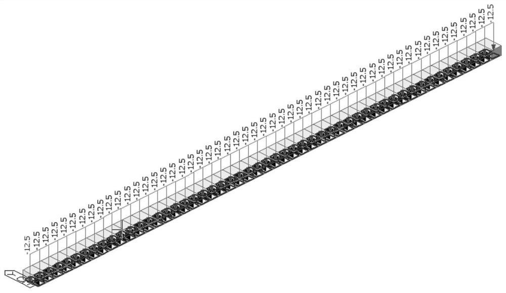
[0083] In order to judge the effective range of the formula derivation in this embodiment, take a simply supported girder bridge as an example, the minimum height of clearance under the bridge is 6.0 meters, the vehicle load level is road-I level, and supports are set on the strip foundation Spiral steel pipe, such as image 3 shown. The pouring height of the first stage is 500mm, and when the first floor beam is a simply supported beam, the pouring height of the first floor should account for 0.3-0.7 of the total height, and the pouring height of the second stage is 500mm, and the priority is given to setting the construction joints near the neutral axis, and dividing the construction joints Finally, the second-floor pouring layer is equivalent to a support system that transmits uniformly distributed loads to the first floor. The coefficient of foundation foundation is 80000KN / m. According to the actual working conditions, the Midas model defines the concrete material as C...


PUM


Abstract

The invention relates to the field of bridge and culvert engineering in the transportation industry, and specifically discloses a construction method for layered pouring of concrete beams on soft ground. This construction method is based on the theory of elastic mechanics, deduces the stress function of the first layer concrete beam during the second layer concrete pouring process, and determines the first layer concrete beam according to the compressive strength test value of the same batch of concrete cube test blocks of the first layer concrete beam The elastic coefficient of the composite foundation under the stress safety condition. According to the elastic coefficient of the composite foundation, the elastic coefficient of the composite foundation is changed to a reasonable and safe range by partial replacement or direct grouting, thereby forming a safer composite foundation to improve its stability. This method can effectively guide the construction of layered concrete beams under soft foundations, and is beneficial to control the early strain of the beams and reduce the late creep, thereby reducing the probability of cracks in the concrete. It will also be more applicable in practice.

Description

technical field [0001] The invention relates to the field of bridge and culvert engineering in the transportation industry, in particular to a construction method for layered pouring of concrete beams on soft ground. Background technique [0002] Concrete bridges are widely used in bridge construction due to their good mechanical performance, serviceability and construction maturity. Most of the concrete beams are not casted in one time, especially the concrete beams with high beam height or complex detailed structure, generally need to be poured multiple times. For cast-in-place brackets, especially for concrete beams that are supported by full brackets and cast in layers, there are many reasons such as poor shrinkage of layered concrete, settlement of brackets, concrete hydration temperature drop, construction technology, etc. Cracks in the concrete will accelerate the carbonation of the concrete and reduce the corrosion resistance of the structure, and eventually reduce ...

Claims


Application Information

Patent Timeline
Patent Type & Authority Patents(China)
IPC IPC(8): E01D21/00E01D101/26
CPCE01D21/00E01D2101/26
Inventor 姚鑫玉蔡宇鹏罗克文王龙林陈基鹏黄凯楠
Owner GUANGXI TRANSPORTATION SCI & TECH GRP CO LTD
Learn More