High-efficiency tunnel cooling vehicle

A high-efficiency, tunnel-based technology, applied in mine/tunnel ventilation, mining equipment, earthwork drilling and mining, etc., can solve problems affecting the efficient operation of construction equipment, affecting construction personnel, and low heat exchange efficiency, achieving simple structure and improved Construction efficiency and cooling effect are obvious

Inactive Publication Date: 2020-08-21
中国铁建投资集团有限公司
View PDF4 Cites 0 Cited by
  • Summary
  • Abstract
  • Description
  • Claims
  • Application Information

AI Technical Summary

Problems solved by technology

[0003] The invention provides a high-efficiency tunnel cooling vehicle to overcome the low heat exchange efficiency and cooling efficiency of the existing conventional tunnel cooling devices, and the cooling process greatly increases the environmental humidity, which affects the labor force and health of construction personnel and affects the efficiency of construction equipment. run problem

Method used


Image

  • High-efficiency tunnel cooling vehicle
  • High-efficiency tunnel cooling vehicle

Examples


Embodiment Construction

[0017] Specific embodiments of the present invention will be described below with reference to the accompanying drawings.

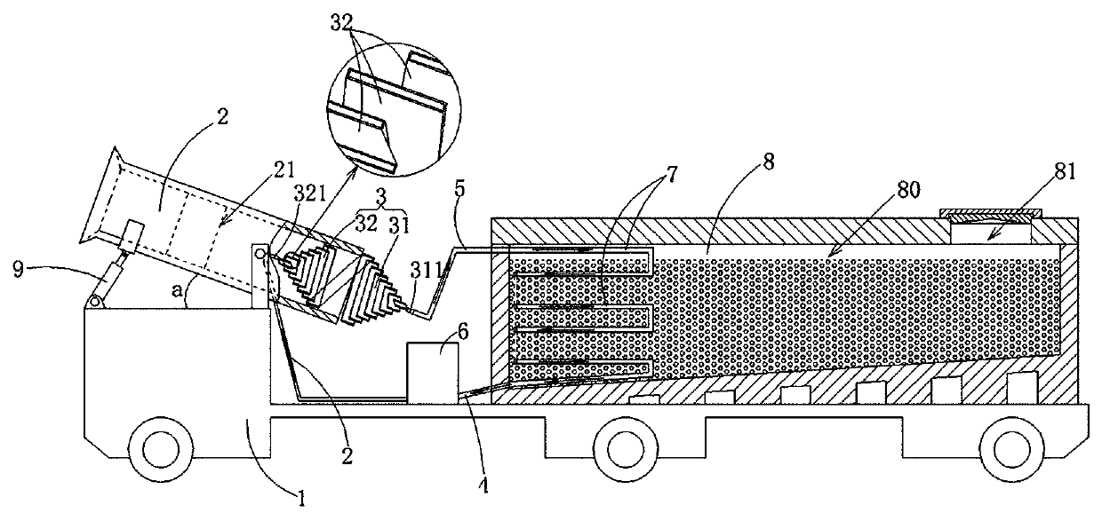
[0018] refer to figure 1 , figure 2 , the high-efficiency tunnel cooling vehicle of the present embodiment, which includes a carrier vehicle 1 and a jet fan 2 assembled on the carrier vehicle 1, an air grid 3, a liquid supply pipe 4, a liquid return pipe 5, a circulation pump 6, and a heat exchanger 7 and closed freezer 8.

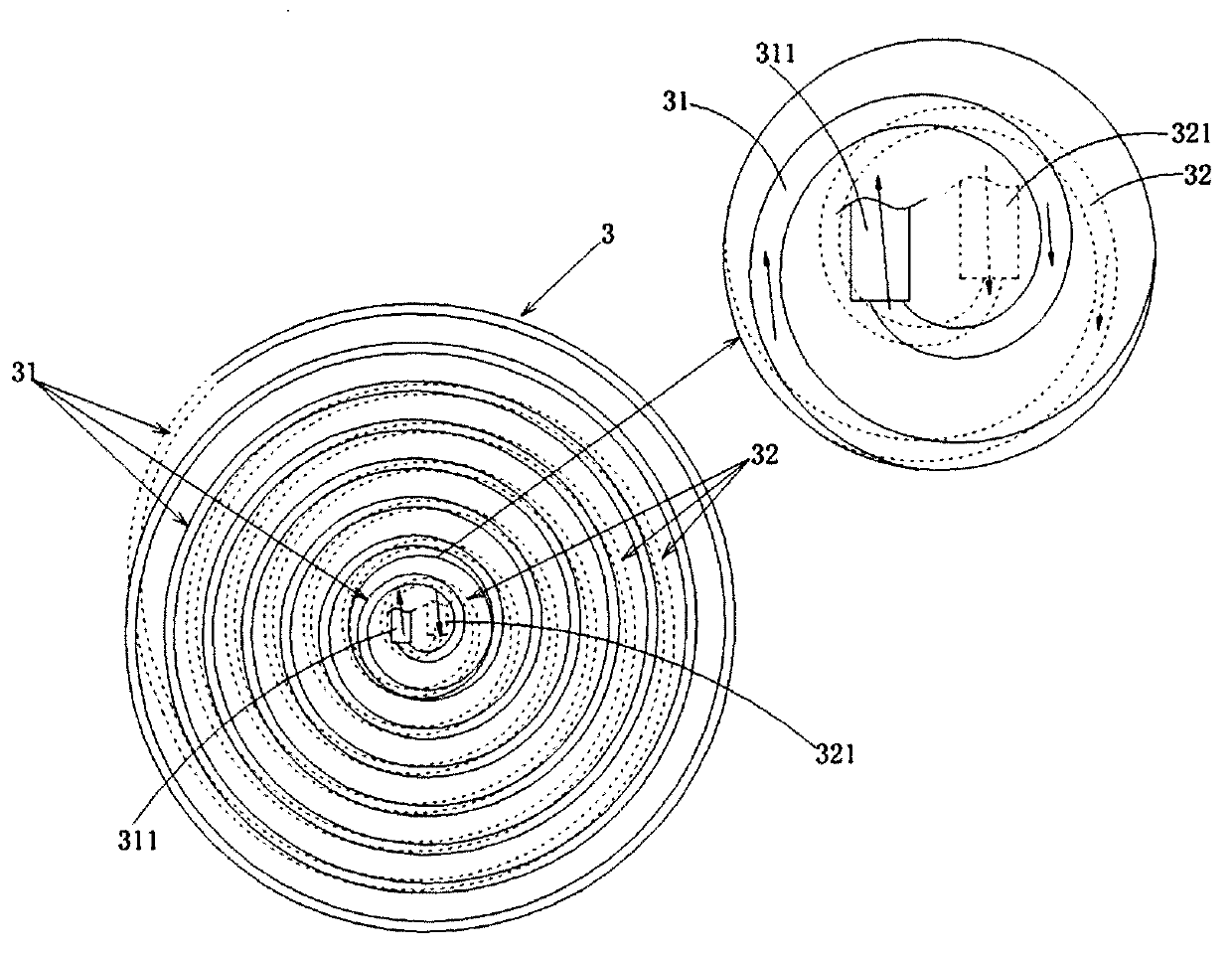
[0019] The above-mentioned air grid 3 includes a pre-cooling air grid 31 and a second cooling air grid 32. The pre-cooling air grid 31 and the second cooling air grid 32 are all formed by a single pipe in a spiral curved conical structure. The liquid outlet of the second cooling air grid 32 is connected to the The liquid inlet end of the pre-cooling air grid 31 is connected and fixedly connected as a whole. The two cooling air grids 32 are fixedly installed inside the air inlet end of the above-mentioned jet fan 2 , and the conica...


PUM


Abstract

The invention relates to a high-efficiency tunnel cooling vehicle which comprises a carrying cart, and a jet fan, a secondary cooling air grid, a liquid feed pipe, a liquid return pipe, a circulatingpump, a heat exchanger and a sealing refrigerator assembled on the carrying cart. Spiral cone faces of a pre-cooling air grid and the secondary cooling air grid of air grids are arranged as connectedstructures; and the circulating pump drives heat-exchange liquid to continuously flow in a one-way circulation way along the liquid outlet end of the heat exchanger, the liquid feed pipe, the circulating pump, the liquid supply pipe, the liquid inlet end of the secondary cooling air grid, the secondary cooling air grid, the pre-cooling air grid, the liquid outlet end of the pre-cooling air grid, the liquid return pipe, the liquid inlet end of the heat exchanger, and the inner part of the heat exchanger. High-temperature air can be high-efficiently low-humidity pre-cooled and fast-cooled, and under the guiding of spiral pipelines of the air grids, when the air passes through the air grids, a rotational flow with a high-efficient stirring function can be produced inside, so that the air canuniformly, high-efficiently and comprehensively transmit heat to the air grids so as to be high-efficiently cooled, the original humidity of a construction environment is maintained since no liquid fog is produced, and a cooling effect is remarkable.

Description

technical field [0001] The invention relates to the field of tunnel cooling equipment, in particular to a tunnel cooling ventilation device with low-humidity air supply. Background technique [0002] During the construction of railways and expressways, tunnel construction projects are often encountered. In the construction of tunnels, high rock temperature is often encountered, which leads to high construction environment temperature (the Sangzhuling Tunnel of Sichuan-Tibet Railway with the highest rock temperature currently encountered The rock temperature is 81.9°C). When the construction temperature is higher than the temperature in the tunnel of 28°C stipulated in the "Railway Tunnel Construction Code" TB10120-2002, the high ground temperature and heat disaster in the tunnel will reduce the labor capacity of the construction workers, have a great impact on health, and the incidence of altitude sickness will increase significantly, and mechanical equipment will fail. The...

Claims


Application Information

Patent Timeline
Patent Type & Authority Applications(China)
IPC IPC(8): E21F3/00E21F1/00
CPCE21F1/003E21F3/00
Inventor 林福地黄君
Owner 中国铁建投资集团有限公司
Why Eureka
Try Eureka