

Organic vegetable planting device
A planting device, a technology for organic vegetables, applied in planting methods, planter parts, sowing planters, etc., can solve the problems of unfavorable vegetable growth and the inability to ensure the same spacing between vegetables, and achieve the effect of avoiding seed rolling
- Summary
- Abstract
- Description
- Claims
- Application Information
AI Technical Summary
Problems solved by technology
Method used
Image

Examples
specific Embodiment approach 1
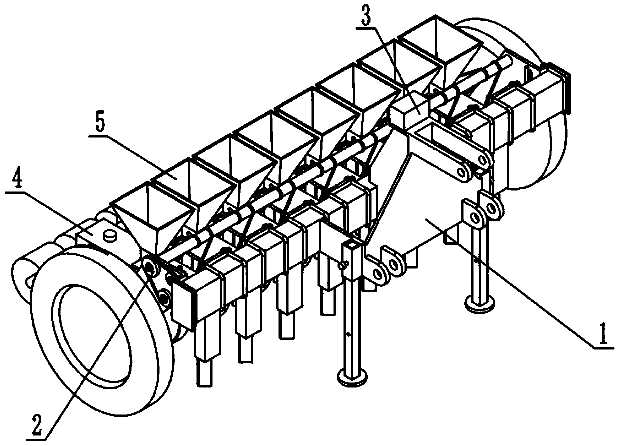
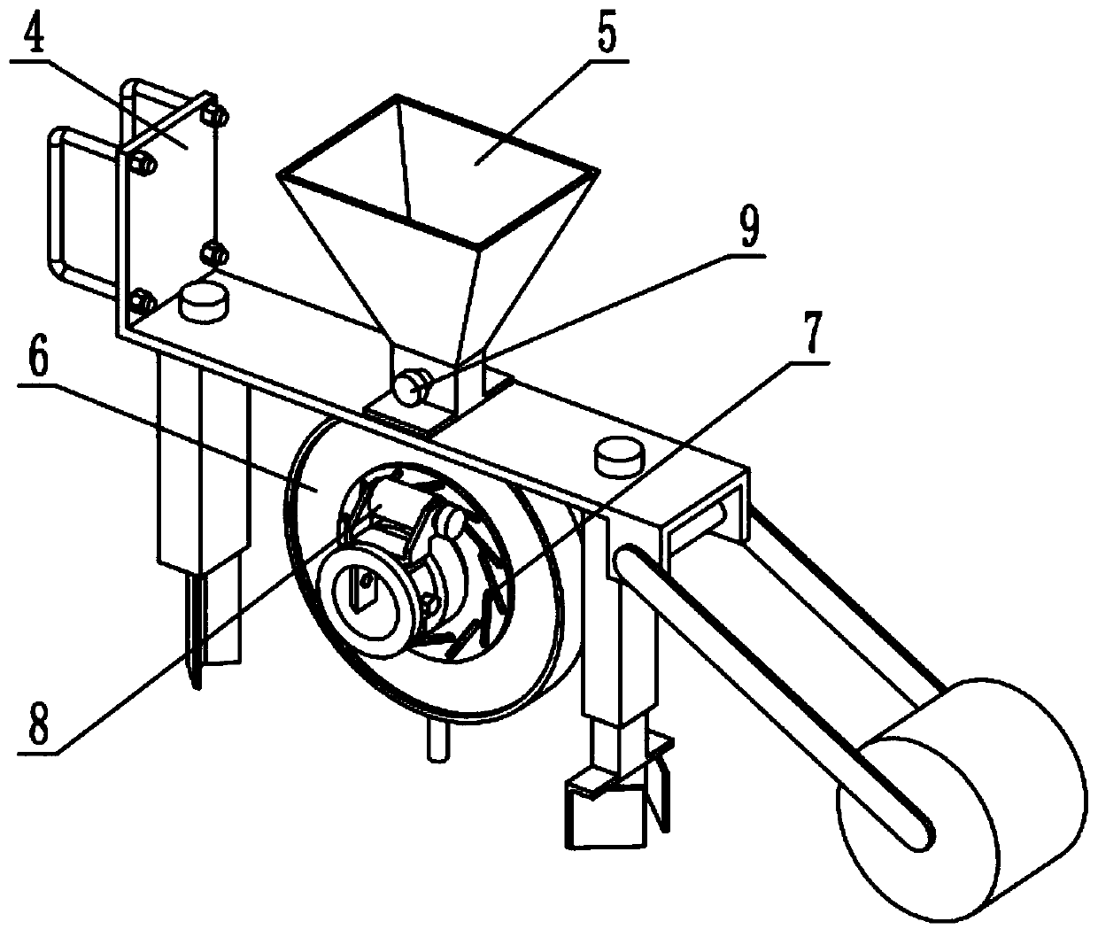
[0033] Such as Figure 1-14 As shown, an organic vegetable planting device includes a main frame mechanism 1, a transmission mechanism 2, an air pump 3, a sub-frame mechanism 4, a seed box mechanism 5, a seeding mechanism 6, a seed supporting mechanism 7, a seed adjusting mechanism 8, Stirring mechanism 9 and shaft center mechanism 10, described transmission mechanism 2 is connected on the main frame mechanism 1, and described air pump 3 is fixedly connected on the main frame mechanism 1, and described sub-frame mechanism 4 is provided with multiple, many Each sub-frame mechanism 4 is fixedly connected on the main frame mechanism 1, and a plurality of sub-frame mechanisms 4 are fixedly connected with a seed box mechanism 5, and a plurality of seed box mechanisms 5 are rotatably connected with a seeding mechanism 6, and each seeding mechanism There are a plurality of seed grain supporting mechanisms 7 slidingly connected in the 6, and a seed grain adjustment mechanism 8 is rota...
specific Embodiment approach 2
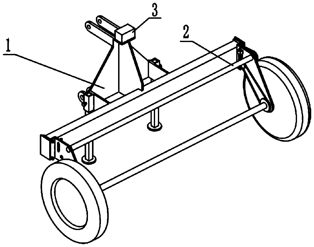
[0036] Such as Figure 1-14 As shown, the main frame mechanism 1 includes a main beam 1-1, a side plate 1-2, a moving wheel 1-3, a leg 1-4, a traction frame 1-5, a tensioning carriage 1-6, a limiter Position bolt 1-7 and mobile axle 1-8, traction frame 1-5 are fixedly connected in the middle part of main beam 1-1, both ends of main beam 1-1 are all fixedly connected with side plate 1-2, mobile axle 1- 8 is rotatably connected to the two side plates 1-2, the two ends of the moving wheel shaft 1-8 are fixedly connected to the moving wheel 1-3, and the tensioning carriage 1-6 is fixedly connected to the side plate 1-2 at the right end , there are two outriggers 1-4, the two outriggers 1-4 are slidingly connected to the two ends of the traction frame 1-5 respectively, there are two limit bolts 1-7, two limit bolts 1-7 Slidingly connected with the two outriggers 1-4 respectively and fixedly connected with the traction frame 1-5 through threads, the air pump 3 is fixedly connected ...
specific Embodiment approach 3
[0039] Such as Figure 1-14 As shown, the transmission mechanism 2 includes a transmission shaft 2-1, a transmission sprocket I2-2, a fixing bolt I2-3, a transmission sprocket II2-4, a fixing bolt II2-5, a transmission wheel shaft 2-6, and a spring 2 -7. The tensioning wheel 2-8 and the tensioning wheel seat 2-9, the transmission shaft 2-1 are connected in rotation on the two side plates 1-2, and the transmission sprocket I2-2 is fixedly connected to the The right end of the transmission shaft 2-1, the transmission wheel shaft 2-6 is rotatably connected to the side plate 1-2 located at the right end, the transmission sprocket II 2-4 is fixedly connected to the right end of the transmission wheel shaft 2-6 through the fixing bolt II 2-5, and the spring 2-7 is sleeved on the tensioning carriage 1-6, the tensioning wheel 2-8 is rotatably connected to the tensioning wheel seat 2-9, and the tensioning wheel seat 2-9 is slidably connected to the tensioning carriage 1-6 On, the spri...
PUM
 Abstract
Description
Claims
Application Information