Eureka AIR delivers breakthrough ideas for toughest innovation challenges, trusted by R&D personnel around the world.

A load control system and method for a cement ball mill

A load control, cement ball technology, applied in grain processing and other directions, can solve the problems of noise amplification effect, larger error, large initial control force, etc., and achieve the effect of solving error amplification

Active Publication Date: 2021-12-10
浙大宁波理工学院
View PDF4 Cites 0 Cited by
  • Summary
  • Abstract
  • Description
  • Claims
  • Application Information

AI Technical Summary

Problems solved by technology

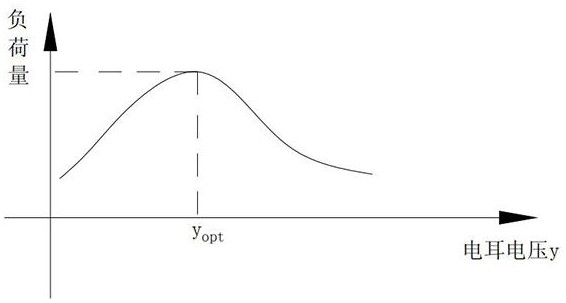
In recent years, microcomputer automatic batching systems have been widely used in many cement plants in my country, but the automatic monitoring of cement ball mill load is still in a relatively backward state. Most cement plants still rely on manual judgment and manual operation, resulting in that the load of the mill cannot be maintained at Optimal state, high energy consumption, low output, and difficult to guarantee quality
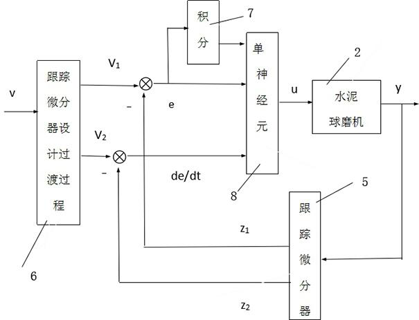
[0004] At present, the most common method is to adjust through the PID control method of "elimination of errors based on error feedback". Since "elimination of errors based on error feedback" is the essence of PID control technology, in actual situations, the relationship between the target and the actual behavior is directly taken. The error often makes the initial control force too large and causes the system behavior to overshoot, which is the main reason for the irreconcilable contradiction between "rapidity" and "overshoot" in the closed-loop system using PID control technology. Therefore, the traditional PID control The differential link of the differentiator is unreasonable to extract the error differential. If the input signal contains noise, the traditional differentiator will easily lead to serious noise amplification effect, and the influence of noise will directly cause the error to increase, and finally the load control does not meet the requirements. asked questions

Method used


Image

  • A load control system and method for a cement ball mill
  • A load control system and method for a cement ball mill
  • A load control system and method for a cement ball mill

Examples


Embodiment 1

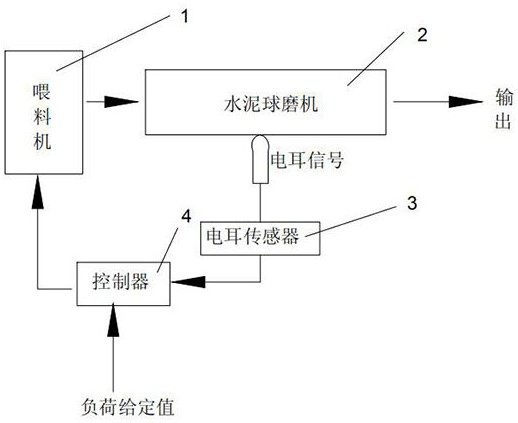
[0043] Such as figure 1 As shown, the load control system of a cement ball mill provided in this embodiment includes the following components:

[0044] A feeder 1 capable of conveying materials;

[0045] Cement ball mill 2 for grinding the material delivered by feeder 1;

[0046] An electric ear sensor 3 located outside the cement ball mill 2 and used to detect the material filling rate in the cement ball mill 2;

[0047] Electrically connected with the electric ear sensor 3, and pre-stored with a controller 4 with a given range of load;

[0048] Wherein the controller 4 is also electrically connected with the feeder 1, and after obtaining the real-time load signal of the electric ear sensor 3 in real time, it is compared with the preset load given range to optimize the environmental impact of the cement ball mill during work. The problem of the influence of the feeding amount of the feeder 1, and finally obtain a suitable feeding amount, so as to realize the process of aut...


PUM


Abstract

The invention discloses a load control system for a cement ball mill, comprising the following components: a feeder; a cement ball mill for grinding the materials conveyed by the feeder; Electric ear sensor; a controller electrically connected with the electric ear sensor and pre-stored with a given range of load; wherein the controller is also electrically connected with the feeder, and after obtaining the real-time load signal of the electric ear sensor in real time , compared with the preset load given range, and then optimize the impact of the environment on the feeding amount of the feeder during the working process of the cement ball mill, and finally obtain the appropriate feeding amount, so as to realize the automatic effect of the environment on the feeding amount. adjustment process. The invention also discloses a load control method of the cement ball mill. The invention can effectively solve the problem of error amplification caused by noise affecting a given value during the load control process of the cement ball mill.

Description

technical field [0001] The invention relates to the field of cement ball mill control, in particular to a cement ball mill load control system and a method thereof. Background technique [0002] Cement ball mill is mainly used in the grinding of finished products and raw materials in cement plants, and is also suitable for grinding various ores and other grindable materials in metallurgy, chemical industry, electric power and other industrial and mining enterprises: when working, the materials are fed by the feeding device through the feeding hollow shaft The spiral evenly enters the first warehouse of the cement ball mill. There are stepped lining boards or corrugated lining boards in the warehouse, and steel balls of different specifications are installed inside. The centrifugal force generated by the rotation of the cylinder will bring the steel balls to a certain height and then fall down, causing heavy impact and grinding on the materials. effect. Materials get coarse ...

Claims


Application Information

Patent Timeline
Patent Type & Authority Patents(China)
IPC IPC(8): B02C25/00B02C17/18
CPCB02C25/00B02C17/183
Inventor 张智焕
Owner 浙大宁波理工学院
Why Eureka
Eureka Blog
Learn More