
Elutriation device applied to chemical plastic materials

A technology for plastics and materials, which is applied in the field of elutriation devices for chemical plastic materials, can solve the problems that the safety of workers cannot be guaranteed, affect the yield of downstream products, increase production costs, etc., and facilitate installation, expand the area, and improve The effect of work efficiency

Pending Publication Date: 2020-08-25
SHANDONG ZHANGQIU BLOWER
View PDF0 Cites 0 Cited by
  • Summary
  • Abstract
  • Description
  • Claims
  • Application Information

AI Technical Summary

Problems solved by technology

[0002] In the production process of polyolefin products and similar engineering plastic raw materials, the products need to be made into granules or sliced. In the production process of making granules or slicing, a very important link is the production of granulation or slicing equipment. The products are sent to the finished product silo or mixing silo by airflow for storage and transportation. During the airflow conveying process of plastic materials, friction and collision will occur between plastic materials and material gas conveying pipelines, resulting in static electricity, dust, wire drawing The combination of static electricity and dust is prone to dust explosion, which has great potential safety hazards, and the safety of staff cannot be guaranteed. The appearance of wire drawing will reduce the quality of products and affect the yield of downstream products. Qualified plastic materials Need special equipment for cleaning, which greatly increases the production cost

Method used


Image

  • Elutriation device applied to chemical plastic materials
  • Elutriation device applied to chemical plastic materials
  • Elutriation device applied to chemical plastic materials

Examples


Embodiment Construction

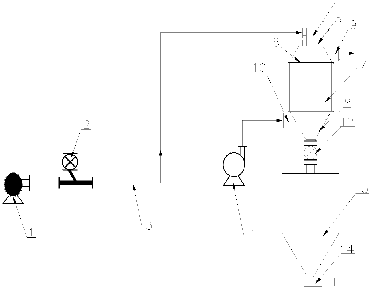
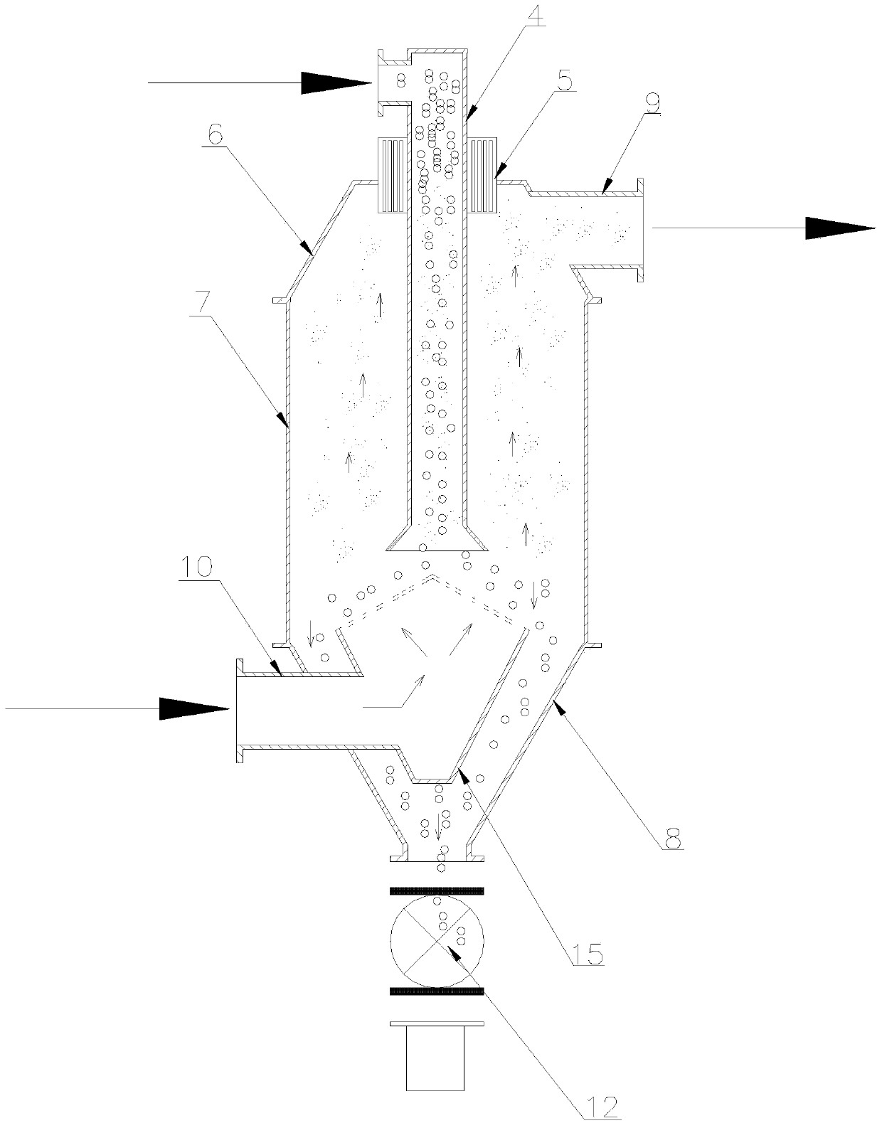
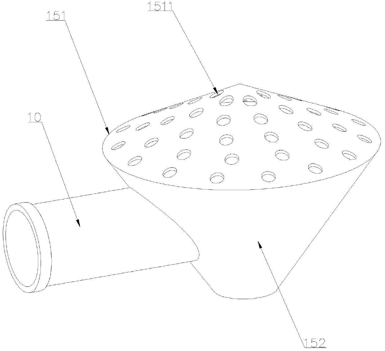
[0025] Attached below Figure 1-4 , clearly and completely describe the technical solutions in the embodiments of the present invention, obviously, the described embodiments are only some of the embodiments of the present invention, not all of them. Based on the embodiments of the present invention, all other embodiments obtained by persons of ordinary skill in the art without making creative efforts belong to the protection scope of the present invention.

[0026] In describing the present invention, it should be understood that the terms "longitudinal", "transverse", "upper", "lower", "front", "rear", "left", "right", "vertical", The orientations or positional relationships indicated by "horizontal", "top", "bottom", "inner", "outer", etc. are based on the orientations or positional relationships shown in the drawings, and are only for the convenience of describing the present invention, rather than indicating or It should not be construed as limiting the invention by imply...


PUM


Abstract

The invention discloses an elutriation device applied to chemical plastic materials. The elutriation device comprises an air source fan, a feeding device, a material gas conveying pipeline, a feedingpipeline, a stock bin and a stock bin discharging valve; one end of the material gas conveying pipeline is connected with the output end of the air source fan, and the other end of the material gas conveying pipeline is connected with a feeding port of the feeding pipeline; and the feeding device is installed on the material gas conveying pipeline and communicates with the material gas conveying pipeline, the stock bin discharging valve is installed at the bottom end of the stock bin, the upper portion of the feeding pipeline is sleeved with a static electricity eliminator, a tank body is arranged below the static electricity eliminator, and the static electricity eliminator and the bottom end of the feeding pipeline extend into the tank body. According to the elutriation device, static electricity generated in the plastic particle conveying process is eliminated through the static electricity eliminator, the dust explosion phenomenon is prevented, the working safety of workers is improved, and plastic materials and dust are separated through an elutriator, so that the cleaning effect is achieved, the production cost is reduced, and the product quality is improved.

Description

technical field [0001] The invention belongs to the technical field of chemical equipment, in particular to an elutriation device applied to chemical plastic materials. Background technique [0002] In the production process of polyolefin products and similar engineering plastic raw materials, the products need to be made into granules or sliced. In the production process of making granules or slicing, a very important link is the production of granulation or slicing equipment. The products are sent to the finished product silo or mixing silo by airflow for storage and transportation. During the airflow conveying process of plastic materials, friction and collision will occur between plastic materials and material gas conveying pipelines, resulting in static electricity, dust, wire drawing The combination of static electricity and dust is prone to dust explosion, which has great potential safety hazards, and the safety of staff cannot be guaranteed. The appearance of wire dr...

Claims


Application Information

Patent Timeline
IPC IPC(8): B08B5/02B08B13/00H05F3/00
CPCB08B5/02B08B13/00H05F3/00
Inventor 部聪令柏泽魁李循刘涛孙波商伟国
Owner SHANDONG ZHANGQIU BLOWER
Learn More