
A guide vane mold and its shrinkage design method

A technology of guide vane and mold shrinkage, which is applied in the field of precision casting, can solve the problems of extended delivery period, blade throat area out of tolerance, and inability to open the mold, so as to promote engineering application, improve design technology, and solve mold opening interference Effect

Active Publication Date: 2021-06-08
AECC AVIATION POWER CO LTD
View PDF0 Cites 0 Cited by
  • Summary
  • Abstract
  • Description
  • Claims
  • Application Information

AI Technical Summary

Problems solved by technology

The invention patent titled a shrinkage rate design method for a multi-blade guide vane precision casting mold discloses a mold design method for setting different shrinkage rates in three directions with large differences in size for turbine guide vanes, which effectively solves the problem. In the past, the throat area of ​​the guide vane was out of tolerance caused by a single shrinkage rate, but this method has the following three problems: First, the multiple joints caused by setting different shrinkage rates in the direction of the edge plate and blade body during mold design. The angle between the blades changes, and angular compensation is required to ensure that the throat area of ​​the blade is qualified; second, due to the different shrinkage ratios set in the direction of the edge plate and the blade body during mold design, the flow surface of the upper edge plate and the lower edge plate The pot mold and the back mold cannot be opened due to the change from a round surface to an elliptical surface; third, in order to ensure the normal mold opening of the mold, it is necessary to rework the mold to remove the obstructing parts, resulting in the size of the runner surface being out of tolerance
[0005] In summary, the shrinkage rate design method of the multi-blade guide vane precision casting mold mentioned above results in an increase in production costs and a prolonged delivery period. Therefore, it is urgent to explore a design method for the shrinkage of turbine guide vane molds without allowance to effectively Ensure that the size is qualified, reduce the repair of the mold, shorten the trial production cycle, and promote the improvement of the precision casting technology of the turbine guide vane

Method used


Image

  • A guide vane mold and its shrinkage design method

Examples


Embodiment 1

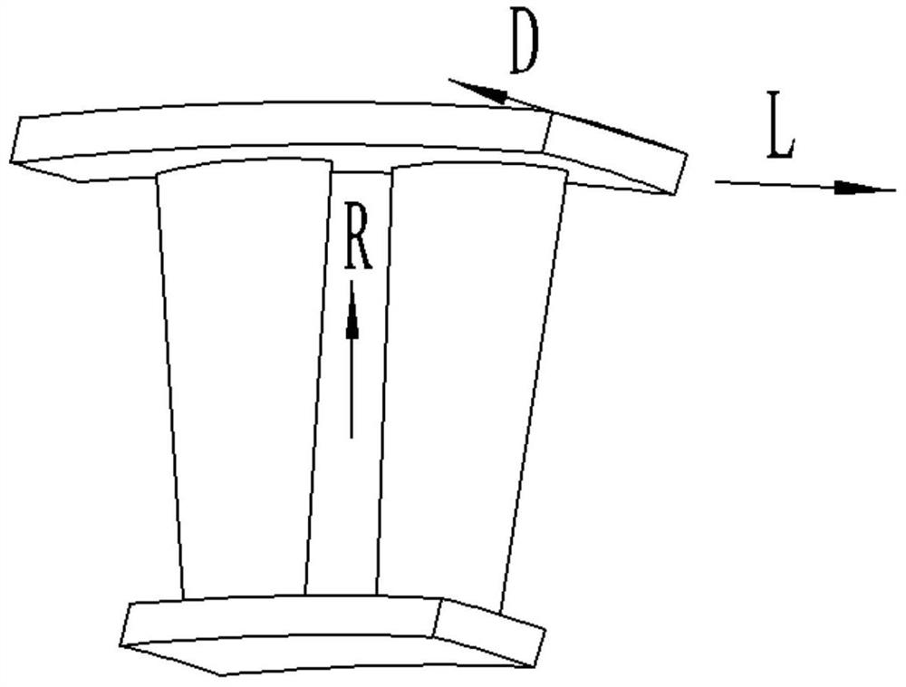
[0053] A slender five-joint equiaxed crystal turbine guide vane of an engine blade:

[0054] Step 1, set parameters

[0055] The length of the blade body is A=225mm; the length direction of the blade is the R direction, which coincides with the coordinate axis Z axis, and the shrinkage rate is ψ1=2.4%;

[0056] The chord length direction of the upper and lower edge plates is the L direction, which coincides with the X axis of the coordinate axis, and the shrinkage rate is ψ2=1.8%;

[0057] The width direction of the upper and lower edge plates is the D direction, which coincides with the coordinate axis Y axis, and the shrinkage rate is ψ3=1.8%.

[0058] Step 2, mold shrinkage setting method

[0059] Taking the origin of the blade engine as the center of the circle, the blade is enlarged as a whole according to the shrinkage rate of 1.8%. The shrinkage rate given in the direction of the blade body is 0.6% smaller than the actual shrinkage rate, and the length of the blade bo...

Embodiment 2

[0062] A single-connected equiaxed crystal turbine guide vane with short blade body and large edge plate in an engine:

[0063] Step 1, set parameters

[0064] The blade body length is A=110mm;

[0065] The length direction of the blade is the R direction, which coincides with the coordinate axis Z axis, and the shrinkage rate is ψ1=1.8%;

[0066] The chord length direction of the upper and lower edge plates is the L direction, which coincides with the X axis of the coordinate axis, and the shrinkage rate is ψ2=2.2%;

[0067] The width direction of the upper and lower edge plates is the D direction, which coincides with the coordinate axis Y axis, and the shrinkage rate is ψ3=2.2%.

[0068] Step 2, mold shrinkage setting method

[0069] Taking the origin of the blade engine as the center of the circle, the blade is enlarged as a whole according to the shrinkage rate of 2.2%. The shrinkage rate given in the direction of the blade body is 0.4% larger than the actual shrinkage...

Embodiment 3

[0071] A single directionally solidified turbine guide vane with the same size as the airfoil and edge plate of an engine:

[0072] Step 1, given parameters

[0073] The blade body length is A=180mm;

[0074] The length direction of the blade is the R direction, which coincides with the coordinate axis Z axis, and the shrinkage rate is ψ1=1.6%;

[0075] The chord length direction of the upper and lower edge plates is the L direction, which coincides with the X axis of the coordinate axis, and the shrinkage rate is ψ2=2.1%;

[0076] The width direction of the upper and lower edge plates is the D direction, which coincides with the coordinate axis Y axis, and the shrinkage rate is ψ3=2.1%.

[0077] Step 2, mold shrinkage setting method

[0078] Taking the origin of the blade engine as the center of the circle, the blade is enlarged as a whole according to the shrinkage rate of 2.1%. The shrinkage rate given in the direction of the blade body is 0.5% larger than the actual shr...


PUM


Abstract

The present invention provides a guide vane die and a shrinkage design method thereof, comprising step 1, enlarging the set guide vane die as a whole according to the shrinkage rate of the chord length of the upper edge plate and the lower edge plate to obtain the enlarged guide vane die; step 2. First compare the length of the blade body in the enlarged guide vane mold with the length of the blade body enlarged according to its own shrinkage rate: when the length of the blade body in the enlarged guide blade mold is larger than the length of the blade body after the enlargement of the blade body according to its own shrinkage rate When it is small, the length of the blade body is lengthened first, and the thickness of the upper edge plate and the lower edge plate is reduced at the same time, and then the upper and lower edge plates are thickened; When the length is larger than the length of the blade body enlarged by its own shrinkage rate, the length of the blade body is shortened first, and the thickness of the upper edge plate and the lower edge plate is increased at the same time, and then the upper and lower edge plates are reduced. Thin treatment, complete the design of the guide vane mold shrinkage, and carry out the manufacture of the guide vane mold.

Description

technical field [0001] The invention belongs to the technical field of precision casting, in particular to a guide vane mold and a shrinkage design method thereof. Background technique [0002] The turbine guide vane is composed of blade body, upper edge plate and lower edge plate. The central axis of the upper edge plate flow channel surface and the lower edge plate flow channel surface center axis are the engine axis. The runner surface of the lower edge plate is formed by the basin mold and the back mold of the wax mold. The basin mold and the back mold are led out through the arc-shaped slideway set on the lower template. In the arc direction of the type block, the central axis of the slideway coincides with the central axis of the engine. [0003] With the continuous improvement of thrust-to-weight ratio requirements of the engine, the design requirements for blade body length, twist and edge plate size of the turbine guide vane without margin increase, and the difficu...

Claims


Application Information

Patent Timeline
Patent Type & Authority Patents(China)
IPC IPC(8): B22C9/04B22C9/22
CPCB22C9/04B22C9/22
Inventor 孙礼娜汪国峰段朋国李杨阳任翠东苏航周宝玲徐宁虎
Owner AECC AVIATION POWER CO LTD
Learn More