Manufacturing method of large-diameter thin-wall circular ring of pressure bearing equipment

A technology of pressure-bearing equipment and manufacturing methods, which is applied in the field of manufacturing thin-walled rings, can solve the problems of low production efficiency, high material costs and high manufacturing costs, and achieve the effects of reducing consumption, reducing material costs and manufacturing costs, and improving material utilization.

Inactive Publication Date: 2020-08-25
HARBIN BOILER
View PDF5 Cites 2 Cited by
  • Summary
  • Abstract
  • Description
  • Claims
  • Application Information

AI Technical Summary

Problems solved by technology

[0003] In order to solve the problems of low production efficiency, high material cost and high manufacturing cost in the existing manufacturing method of thin-walled rings, the present invention proposes a manufacturing method of large-diameter thin-walled rings for pressure equipment

Method used


Image

  • Manufacturing method of large-diameter thin-wall circular ring of pressure bearing equipment
  • Manufacturing method of large-diameter thin-wall circular ring of pressure bearing equipment
  • Manufacturing method of large-diameter thin-wall circular ring of pressure bearing equipment

Examples


specific Embodiment approach 1

[0024] Specific implementation mode 1: The manufacturing method of the large-diameter thin-walled ring of the pressure-bearing equipment in this implementation mode is carried out according to the following steps:

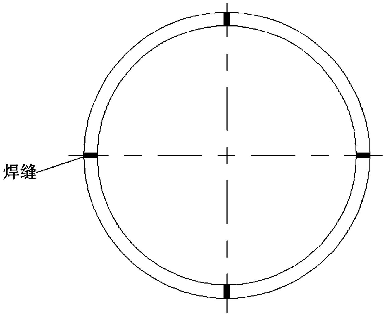
[0025] 1. Scribing and cutting the steel plate to obtain a rectangular steel plate, and process the groove of the longitudinal seam;

[0026] 2. Roll the steel plate obtained in step 1 into a cylinder;

[0027] 3. Tailor welding the longitudinal seam and grinding the weld seam;

[0028] 4. Correct the roundness of the cylinder;

[0029] 5. Install and weld rigid support components in the cylinder;

[0030] 6. Fix one end of the cylinder on the lathe chuck;

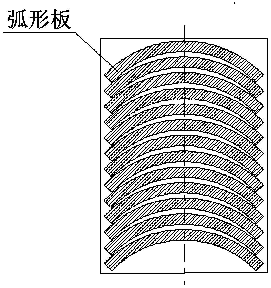
[0031] 7. Cut the cylinder into multiple rings with a turning tool on a lathe;

[0032] 8. Grinding the welding point between the rigid support component and the cylinder to remove the rigid support component and obtain multiple thin-walled rings;

[0033] Nine, grinding edges and burrs.

[0034] This imp...

specific Embodiment approach 2

[0035] Specific embodiment 2: The difference between this embodiment and specific embodiment 1 is that the rigid support assembly described in step 5 includes a plurality of axial support rods 1 welded to the inner wall of the cylinder, and the axial support rods 1 between the axial support rods 1 A plurality of radial rod-shaped support components vertically fixed to the support rod 1. Other steps and parameters are the same as those in the first embodiment. The rigid support component is welded with the cylinder body. The rigid support component can ensure the rigidity, roundness and dimensional stability of the cylinder body. After processing, the rigid support component can be removed by grinding. The rigid support component can be cut with surplus material to reduce costs;

specific Embodiment approach 3

[0036] Embodiment 3: The difference between this embodiment and Embodiment 2 is that the radial rod-shaped support assembly is composed of a plurality of radial support rods 2 , and the plurality of radial support rods 2 are arranged radially and their ends are mutually Fixed. Other steps and parameters are the same as in the second embodiment.


PUM

PropertyMeasurementUnit
thicknessaaaaaaaaaa

Abstract

The invention provides a manufacturing method of a large-diameter thin-wall circular ring of pressure bearing equipment and relates to a manufacturing method of the thin-wall circular ring. The purpose is to solve the problems that the production efficiency of an existing discharging, tailor welding and forming method for a multi-section arc plate steel plate of the large-diameter thin-wall circular ring is low, and the material cost and the manufacturing expense are high. The method comprises the steps that the steel plate is discharged, a longitudinal joint groove is machined, the steel plate is rolled into a cylinder body and subjected to tailor welding, a rigid supporting assembly is installed in the cylinder body in a welding manner, and the cylinder body is cut into multiple circularrings by a turning cutter on a turning lathe. According to the method, the number of machined grooves and the number of weld joints are reduced remarkably, the production efficiency is high, corner excess materials are not generated, the material utilization rate is increased, and the material cost and the manufacturing expense are reduced. The method is applicable to manufacturing of a large-diameter thin-wall circular ring part structure in the pressure bearing equipment.

Description

technical field [0001] The invention relates to a manufacturing method of a thin-walled circular ring. Background technique [0002] Large-diameter thin-walled ring parts in pressure-bearing equipment such as boilers and pressure vessels have large diameters, small cross-sectional dimensions, poor rigidity, high technical requirements, and difficult processing. For a long time, segmental CNC cutting and blanking and tailor welding have been used. figure 1 As shown, the arc-shaped plate is cut on the steel plate, and then the arc-shaped plate is tailor-welded into a ring (such as figure 2 shown); this method produces a lot of waste when cutting and blanking, and the process is complicated. Each large-diameter thin-walled ring part needs to process multiple grooves and tailor welding multiple welds, which leads to low production efficiency, material costs and manufacturing costs. high. Contents of the invention [0003] In order to solve the problems of low production ef...

Claims


Application Information

Patent Timeline
Patent Type & Authority Applications(China)
IPC IPC(8): B23P15/00
CPCB23P15/00
Inventor 袁承春
Owner HARBIN BOILER
Why Eureka
Try Eureka