Vertical adjustable modulus prefabricated staircase forming equipment and its step height adjustment method
A technology for forming equipment and stairs, applied in the direction of molds, etc., can solve the problems of scrapped molds, unable to realize flexible production, and large variation range, and achieve the effect of convenient disassembly.
- Summary
- Abstract
- Description
- Claims
- Application Information
AI Technical Summary
Problems solved by technology
Method used
Image
Examples
Embodiment 1
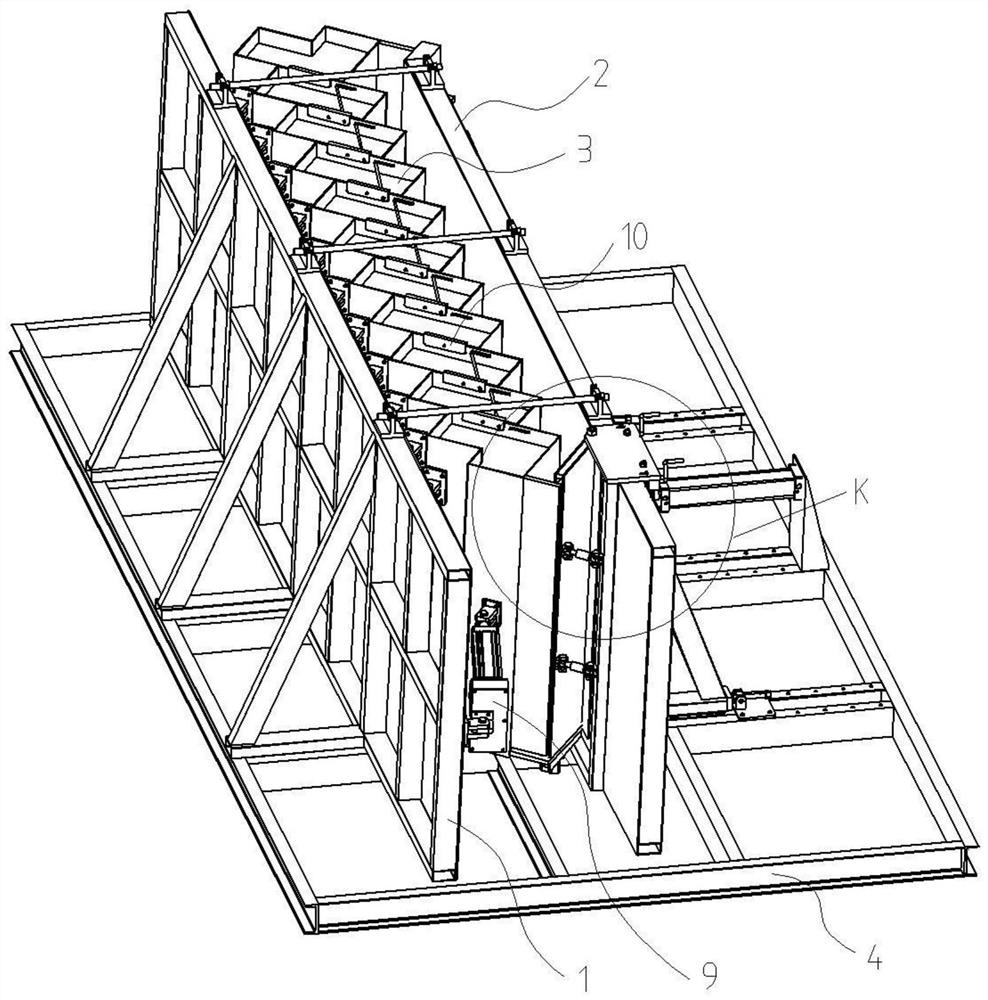
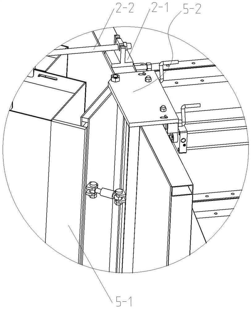
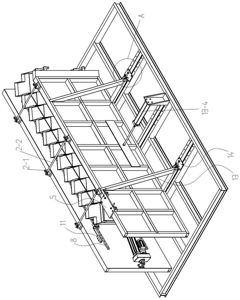
[0062] The base frame 4 is provided with a fixed side form 1, a movable side form 2 and a stair step module 3, the fixed side form 1 is connected with the base frame 4 by bolts, the movable side form 2 is slidably connected with the base frame 4, and the stair step module 3 is connected with the fixed side Die 1 connection. The stair step module 3 comprises a first step end mold 3-1, a second step end mold 3-2 and a plurality of step molds 3-3 between the two; the step mold 3-3 comprises a first end face 3-31, Step surface 3-32 and second end face 3-33 (height), the first step end die 3-1 and the first end face 3-31 of adjacent step die 3-3 offset, the second step end die 3-2 and The second end surfaces 3-33 of adjacent step molds 3-3 are in contact, and the first end surfaces 3-31 of two adjacent step molds 3-3 are in contact with the second end surfaces 3-33. A movable end template 5 , a fixed end template 6 and a bottom template 7 are arranged between the movable side form...
Embodiment 2
[0072] To adapt to the production requirements of different stepping stairs for the convenience of stepping mold 3-3 disassembly, a quick dismounting module 15 is provided between the slide block 8-2 and the stepping mold 3-3. The quick dismounting module 15 includes a connecting seat and a taper pin 15-1, the connecting seat is made up of a rotating plate 15-3 and a rotating seat 15-2, and the rotating plate 15-3 and the rotating seat 15-2 are provided with cones. The hole that type pin 15-1 matches. Rotating plate 15-3 is connected with slide block 8-2 bolts, and rotating seat 15-2 is connected with bolts respectively with the first step end mold 3-1, the second step end mold 3-2 and a plurality of step molds 3-3. When dismounting, the step mold 3-3 is lifted, and after taking off the taper pin 15-1, the step mold 3-3 can be removed; when increasing the step mold 3-3, first connect the rotating plate The slide block 8-2 of 15-3 is installed on the slide rail 8-1, then the s...
Embodiment 3
[0075] The chute synchronizer 10 also includes a bearing 10-4 and a clamping plate 10-5 of a U-shaped structure, and the clamping plate 10-5 is clamped on the edges of the two matching step molds 3-3 and the first step end mold 3 -1. The edge where the second step end mold 3-2 and the step mold 3-3 fit together. To increase the contact area of the stepping mold 3-3, ensure that the stepping mold 3-3 is evenly stressed, and prevent the stepping mold 3-3 from being slightly deformed. The bearing 10-4 is sleeved on the sliding pin shaft 10-1 and matched with the limiting chute 10-3, and a bushing 10-6 is arranged between the bearing 10-4 and the end cover 10-2.
[0076] A guide chute 10-7 is provided on the second end face 3-33 of the step mold 3-3, and a guide chute 10-7 is also provided on the end face of the first step end mold 3-1 and the step mold 3-3. 7. The guide chute 10-7 and the limiting chute 10-3 are arranged symmetrically. The first end face 3-31 of the stepping ...
PUM
 Abstract
Description
Claims
Application Information
 - R&D
- Intellectual Property
- Life Sciences
- Materials
- Tech Scout
- Unparalleled Data Quality
- Higher Quality Content
- 60% Fewer Hallucinations
Browse by: Latest US Patents, China's latest patents, Technical Efficacy Thesaurus, Application Domain, Technology Topic, Popular Technical Reports.
© 2025 PatSnap. All rights reserved.Legal|Privacy policy|Modern Slavery Act Transparency Statement|Sitemap|About US| Contact US: help@patsnap.com


