
Bucket type Z-type conveyor

A conveyor and bucket-type technology, applied in the field of bucket-type Z-type conveyors, can solve the problems of poor airtightness, human injury, and high production costs, and achieve flexible equipment installation and layout, convenient installation and disassembly, and high work efficiency. Effect

Pending Publication Date: 2020-08-25
张家港保税区港中源机械科技有限公司
View PDF0 Cites 2 Cited by
  • Summary
  • Abstract
  • Description
  • Claims
  • Application Information

AI Technical Summary

Problems solved by technology

[0002] In the existing material conveying device, the airtightness of the material in the material conveying device is not very good during the conveying process, which is prone to material leakage, and in the material conveying environment with a high drop, the material is easy to fall off in the hopper, and if the height If the drop is very large, a large-scale material conveying device is required, and the production cost is also high. In the process of conveying some chemical and toxic materials, the corrosion hopper itself will be damaged
Therefore, most of the work positions with height difference, some of which are manually transported to the work table with a height of several meters, but some chemical materials are poisonous, easy to corrode, polluted, and have high acid-base concentration, which will cause harm to the human body. Certain damage, the sealed Z-type conveyor produced by our company solves the problem of mechanical replacement of labor
Because of the particularity of the hopper, there will be a gap between the hopper and the hopper, and problems such as material leakage, throwing, spilling, and damage to the shape and characteristics of the material will occur during transportation.

Method used


Image

  • Bucket type Z-type conveyor
  • Bucket type Z-type conveyor
  • Bucket type Z-type conveyor

Examples


Embodiment Construction

[0020] Below in conjunction with specific embodiment, content of the present invention is described in further detail:

[0021] The problem to be solved by the present invention is to provide a bucket type Z-type conveyor with high efficiency, energy saving, strong adjustability, and effectively reducing problems such as spillage during material transportation.

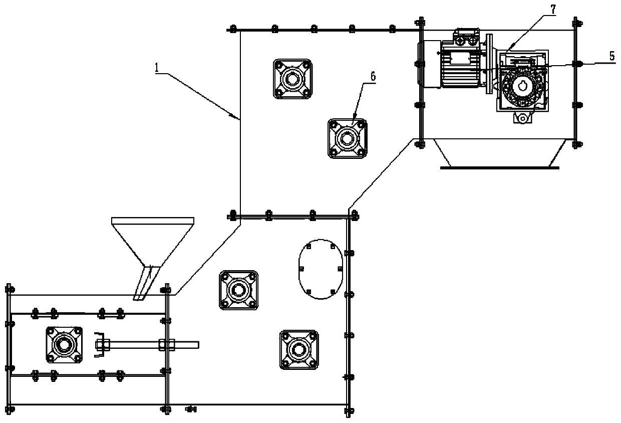
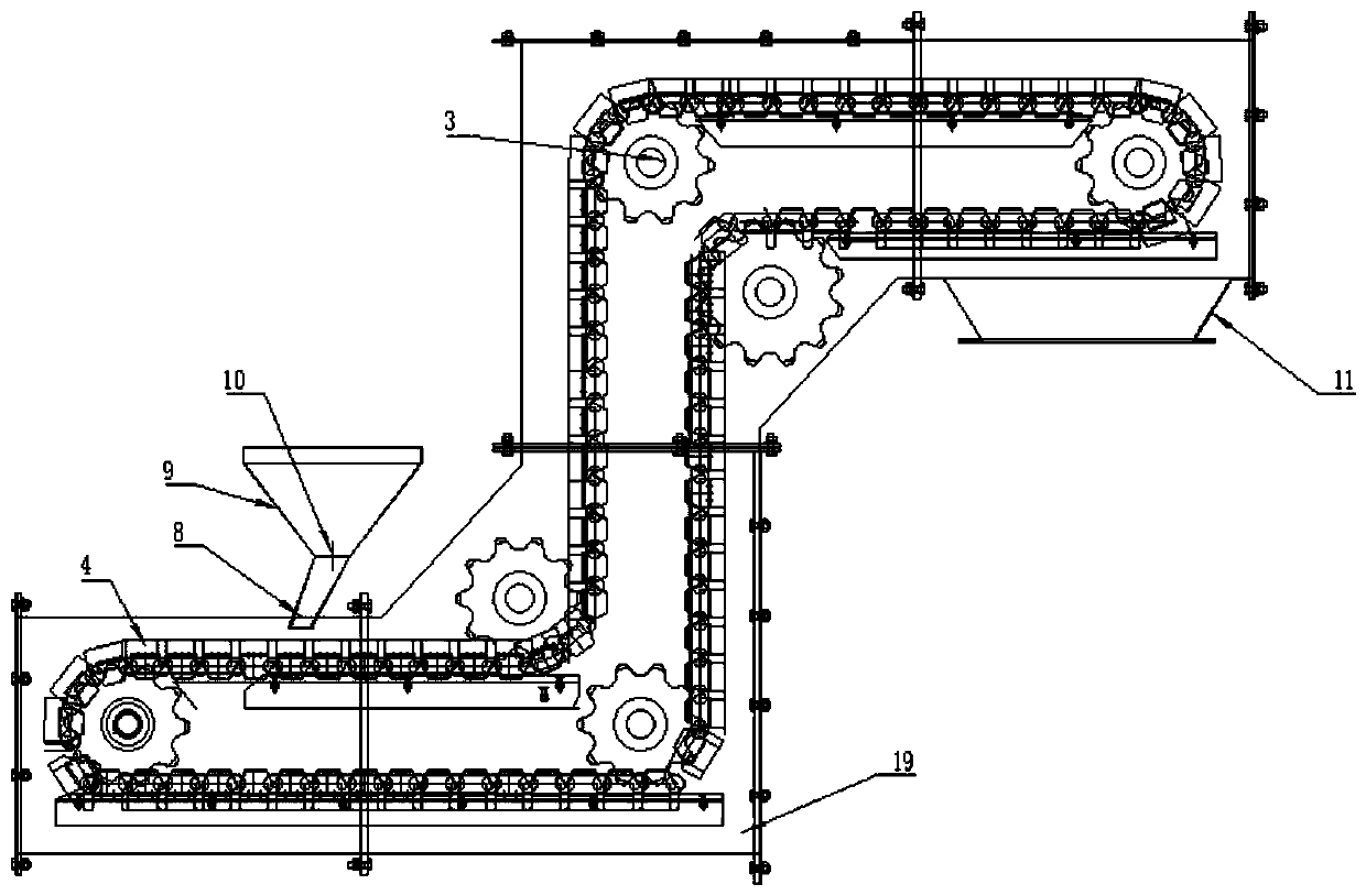
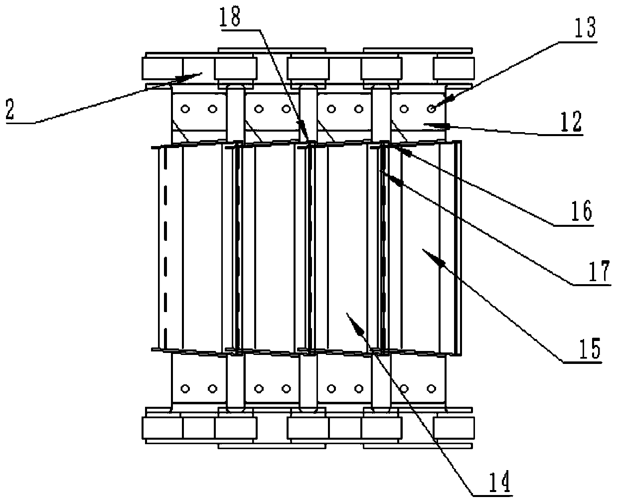
[0022] Such as figure 1 , figure 2 As shown, in order to ensure stable operation and high work efficiency during use, the present invention relates to a bucket type Z-type conveyor, including:

[0023] Housing 1, transmission chain 2, sprocket 3, hopper 4, motor 5;

[0024] The housing 1 is provided with a sprocket fixing device 6; the sprocket 3 is fixed inside the housing 1 through the sprocket fixing device 6; the transmission chain 2 is connected with the sprocket 3; The sprocket 3 is symmetrically arranged left and right in the housing 1; the hopper 4 is connected and fixed with the transmission chain 2; the ...


PUM


Abstract

The invention relates to a bucket type Z-type conveyor which comprises a shell, a transmission chain, chain wheels, hoppers and a motor. A chain wheel fixing device is arranged on the shell. The chainwheels are fixed in the shell through the chain wheel fixing device. The transmission chain is connected with the chain wheels. The chain wheels are arranged in the shell in bilateral symmetry. The hoppers and the transmission chain are connected and fixed. A motor fixing frame is arranged at the upper end of the shell, and the motor and the shell are connected and fixed through the motor fixingframe. By means of the bucket type Z-type conveyor, dust in the shell can be prevented from adsorbed out to the outer environment; through the secondary and primary hopper design, the defects of material missing, scattering and the like cannot be caused; by means of a food-grade plastic film, safety and sanitation are guaranteed, materials cannot impact on the hoppers, the plastic film can effectively reduce the connecting gap between the hoppers, the problems of hopper metal friction material scattering and the like are effectively solved, material integrity is guaranteed, and the rapid boltconnecting shell is convenient to mount and dismounted; and multiple conveyors are fixedly connected to be used, and practicality is high.

Description

technical field [0001] The invention relates to the field of mechanical material transportation, in particular to a bucket Z-type conveyor. Background technique [0002] In the existing material conveying device, the airtightness of the material in the material conveying device is not very good during the conveying process, which is prone to material leakage, and in the material conveying environment with a high drop, the material is easy to fall off in the hopper, and if the height If the drop is large, a large-scale material conveying device is required, and the production cost is also high, and the corrosion hopper itself will be damaged during the conveying of some chemically toxic materials. Therefore, most of the work positions with height difference, some of which are manually transported to the work table with a height of several meters, but some chemical materials are poisonous, easy to corrode, polluted, and have high acid-base concentration, which will cause harm ...

Claims


Application Information

Patent Timeline
Patent Type & Authority Applications(China)
IPC IPC(8): B65G17/12B65G23/06B65G17/30B65G17/36B65G47/40
CPCB65G17/126B65G17/30B65G17/36B65G23/06B65G47/40B65G2201/04
Inventor 周正清乔亚鸽隆玉林
Owner 张家港保税区港中源机械科技有限公司
Learn More