Supercharge Your Innovation With Domain-Expert AI Agents!

Magnetic levitation transmission device

A transmission device and maglev technology, which is applied in electromechanical devices, conveyors, transportation and packaging, etc., can solve the problems of easy damage of friction parts, affecting flexibility, and large maintenance, so as to reduce mechanical friction, ensure accuracy and Comprehensive, low-maintenance results

Pending Publication Date: 2020-08-25
湖南凌翔磁浮科技有限责任公司
View PDF0 Cites 0 Cited by
  • Summary
  • Abstract
  • Description
  • Claims
  • Application Information

AI Technical Summary

Problems solved by technology

[0002] At present, major enterprises and factories widely use mechanical conveyor belts or mechanical linear motors on the production line to transport items. The principle of mechanical conveyor belts is to drive belts or chain plates to move through rotating motors. The converter is converted into linear kinetic energy to drive the mover movement. Due to the inevitable existence of mechanical friction, the mechanical conveyor belt or mechanical linear motor has low efficiency, high noise, easy damage to friction parts, large follow-up maintenance, and low positioning accuracy during transportation. And other problems, and the mover part of the mechanical linear motor also needs to be connected to the cable, and the flexibility will be affected by the constraints of the cable during movement.

Method used


Image

  • Magnetic levitation transmission device
  • Magnetic levitation transmission device
  • Magnetic levitation transmission device

Examples


Embodiment Construction

[0031] Embodiments of the present invention are described in detail below, examples of which are shown in the drawings, wherein the same or similar reference numerals designate the same or similar elements or elements having the same or similar functions throughout. The embodiments described below by referring to the figures are exemplary only for explaining the present invention and should not be construed as limiting the present invention.

[0032] In the description of the present invention, unless otherwise clearly defined, words such as setting, installation, and connection should be understood in a broad sense, and those skilled in the art can reasonably determine the specific meanings of the above words in the present invention in combination with the specific content of the technical solution.

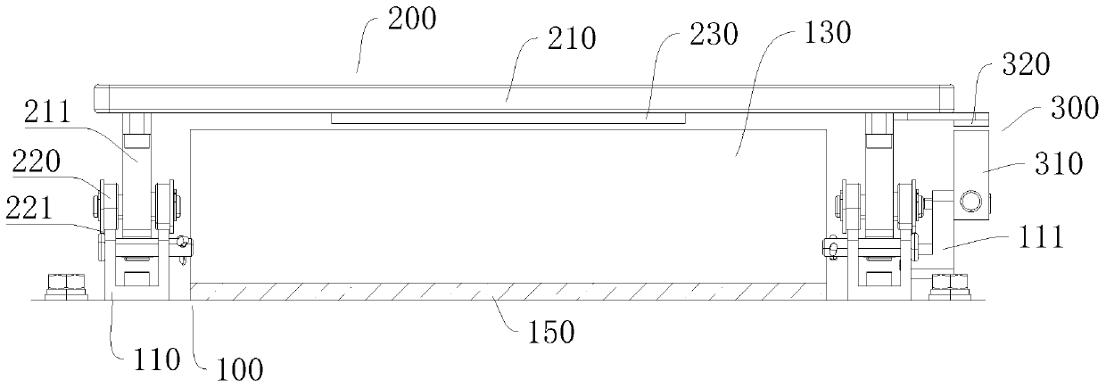
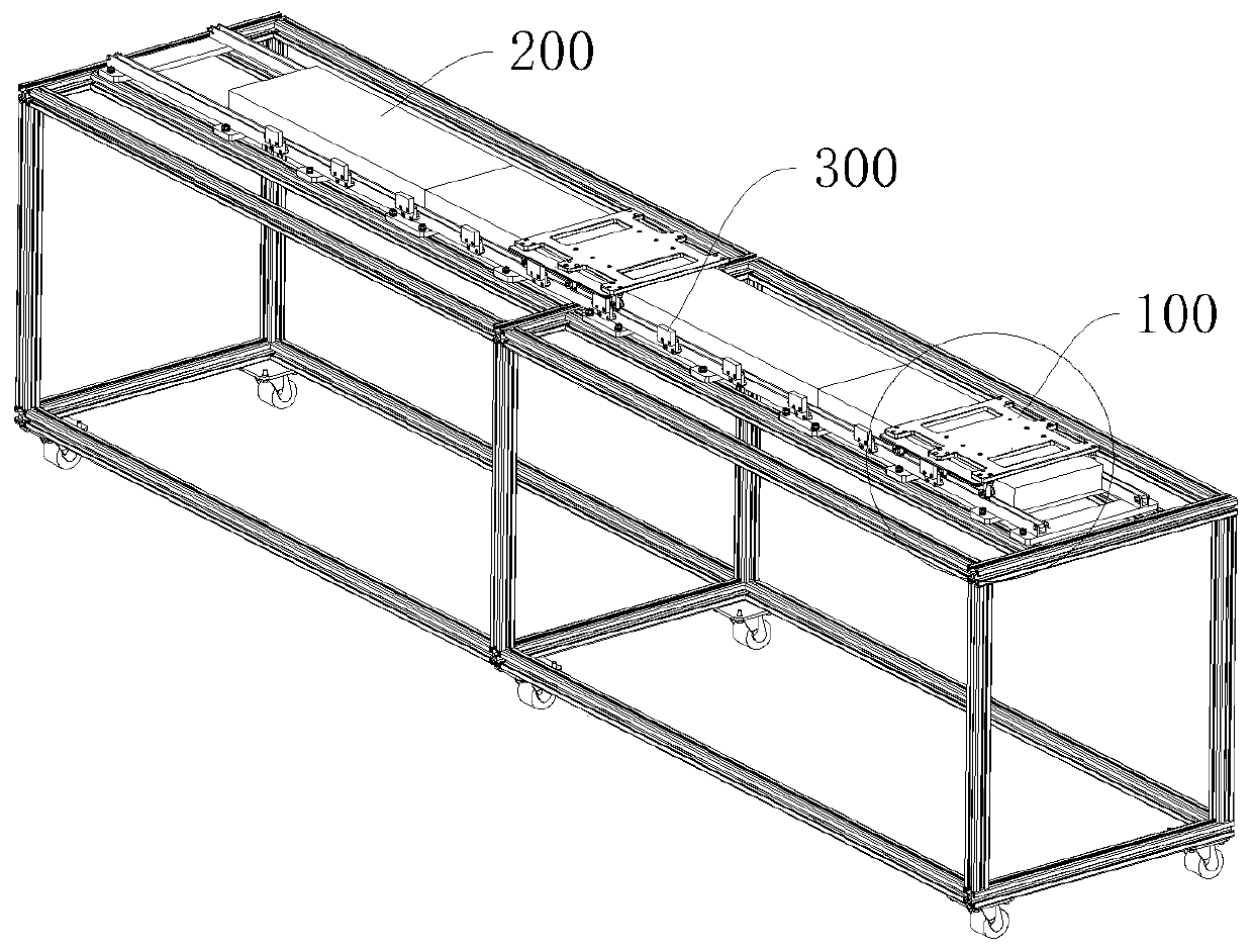
[0033] refer to figure 2 and image 3 , a magnetic levitation transmission device, including: a stator 100, a mover 200, a positioning speed measuring unit 300 and a control ...


PUM


Abstract

The invention discloses a magnetic levitation transmission device. The magnetic levitation transmission device comprises a stator, a mover, a positioning speed measuring unit and a control unit; the stator comprises tracks and iron cores with three-phase windings; the iron cores are distributed along the tracks and positioned in the middles of the tracks; the mover comprises a car body, rollers and permanent magnets; the car body is arranged on the tracks through the rollers in a sliding manner; under the action of a magnetic field formed by the permanent magnets and the iron cores, a tractionforce is formed to drive the mover to slide on the tracks; the positioning speed measuring unit comprises a plurality of magnetic induction sensors and a magnetic grid ruler; the control unit is electrically connected with power supply end magnets of the three-phase windings; and the control unit calculates the position and speed of the rotor through a received induction signal. Compared with a conventional mechanical conveyor belt, the mechanical friction is greatly reduced, the transportation efficiency is high, and the noise is low. Because of the reduction of the mechanical friction, thewhole components are not easy to wear, and the subsequent maintenance amount is low. In addition, the mover does not need to be connected with cables, and is not restricted by the cables when moving,so that the flexibility is high, and the positioning accuracy and comprehensiveness are good.

Description

technical field [0001] The invention relates to the field of transportation equipment, in particular to a magnetic levitation transmission device. Background technique [0002] At present, major enterprises and factories widely use mechanical conveyor belts or mechanical linear motors on the production line to transport items. The principle of mechanical conveyor belts is to drive belts or chain plates to move through rotating motors. The converter is converted into linear kinetic energy to drive the mover movement. Due to the inevitable existence of mechanical friction, the mechanical conveyor belt or mechanical linear motor has low efficiency, high noise, easy damage to friction parts, large follow-up maintenance, and low positioning accuracy during transportation. And other problems, and the mover part of the mechanical linear motor also needs to be connected to the cable, which will be restricted by the cable during movement and affect the flexibility. Contents of the ...

Claims


Application Information

Patent Timeline
IPC IPC(8): B65G54/02H02K41/02
CPCB65G54/02B65G2203/043H02K41/02
Inventor 刘恒坤周文武苏款涂俊陈明丁宇航周晓
Owner 湖南凌翔磁浮科技有限责任公司
Features
  • R&D
  • Intellectual Property
  • Life Sciences
  • Materials
  • Tech Scout
  • Unparalleled Data Quality
  • Higher Quality Content
  • 60% Fewer Hallucinations
Learn More