Lifting device for wall cupboard

A technology of lifting device and hanging cabinet, applied in the direction of lifting device, lifting frame, hoisting device, etc., can solve the problems of low space utilization rate, reducing self-locking force of transmission mechanism, complicated structure of hanging cabinet body, etc., and saving replacement time. and cost, the effect of improving the replacement speed

Pending Publication Date: 2020-08-25
ZHEJIANG JIECHANG LINEAR MOTION TECH
View PDF0 Cites 2 Cited by
  • Summary
  • Abstract
  • Description
  • Claims
  • Application Information

AI Technical Summary

Problems solved by technology

[0002] In modern decoration, in order to improve the utilization rate of space and the overall aesthetics after storage, lifting and hanging cabinets are used in many places such as cabinets, TVs, and dressing tables. There are also various lifting devices used in hanging cabinets, but the lifting devices currently on the market The device itself takes up a lot of space, resulting in a complex structure of the wall cabinet body and low space utilization. In order to solve the above problems, technicians improved it. The transmission mechanism in the lifting device generally adopts a worm and worm gear assembly or a screw nut assembly. The control precision of the mechanism is high, but the lifting speed of the hanging cabinet using this mechanism is relatively slow. If you want to achieve fast operation, you must either increase the lead of the screw or increase the speed of the motor. Increasing the lead of the screw will reduce the self-locking of the transmission mechanism Increasing the motor speed will increase the noise of the transmission mechanism itself

Method used


Image

  • Lifting device for wall cupboard
  • Lifting device for wall cupboard
  • Lifting device for wall cupboard

Examples


Embodiment 1

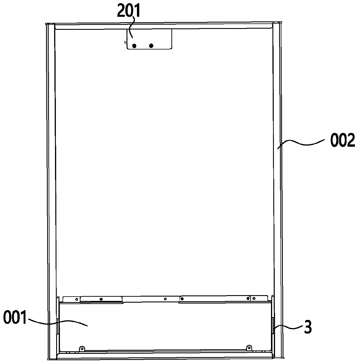
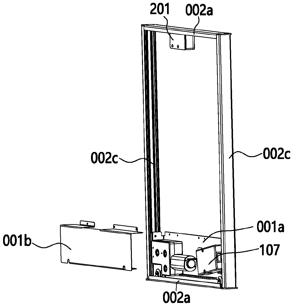
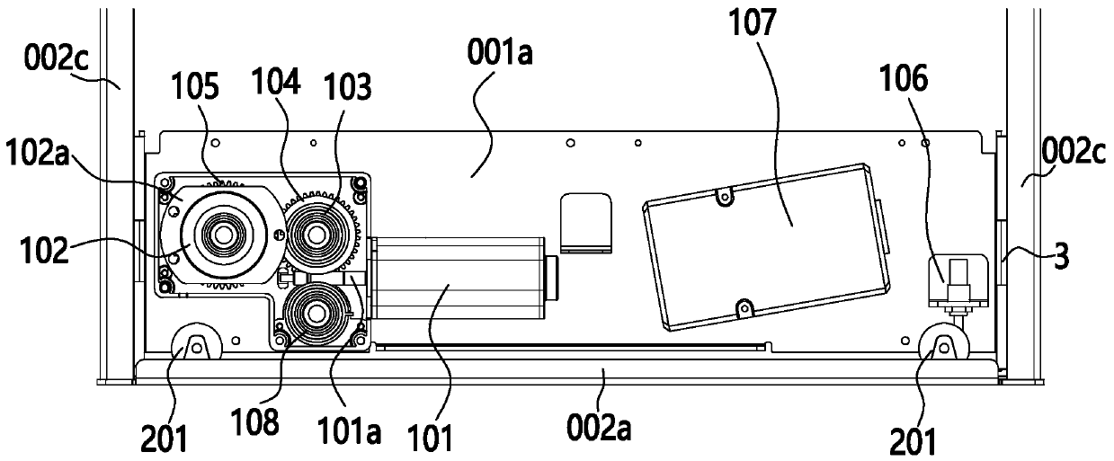
[0041] Such as Figure 1 ~ Figure 3 As shown, a lifting device for a hanging cabinet, the hanging cabinet includes a locker, and the fast lifting device includes a fixed frame 001 fixed on an external firmware, a mobile frame 002 that moves relative to the fixed frame 001, and a connection between the fixed frame 001 and the mobile frame The rope of 002, the locker is detachably connected on the mobile frame 002, the fixed frame 001 is provided with a motor 101 and the reel 102 that rotates and retracts the rope under the drive of the motor 101, drives the mobile frame 002 to move by the retracting of the rope.

[0042] The lifting device in this scheme, the fixed frame 001 can be directly fixed on the wall, or can be fixed on the outer cabinet, and connected to the mobile frame 002 as a hanging basket or an inner cabinet of the locker. The structure is simple and the installation is convenient. The motor 101 drives the reel 102 rotation, through the circumferential movement o...

Embodiment 2

[0053] Such as Figure 5 As shown, the difference between this embodiment and Embodiment 1 is that the fixed frame 001 includes a bottom plate 001a fixed on the external firmware, the reel 102 is arranged in the middle of the bottom plate 001a, and the moving frame 002 includes a lower plate 002b, and the middle of the lower plate 002b is provided with Rope fixing seat 106, one end of the rope is fixed on the reel 102, and the other end of the rope is fixed on the rope fixing seat 106.

[0054] With the above structure, the moving distance of the mobile frame 002 is equal to the length of the circumference of the reel 102, which reduces the stroke of the reel 102 and the length of the steel wire, further improves the lifting speed and shortens the lifting time.

Embodiment 3

[0056] Such as Figure 6 ~ Figure 11 As shown, the difference between this embodiment and Embodiment 1 is that a wing plate 001c is provided at the end of the bottom plate 001a of the fixed frame, and a slider assembly 03 is provided on the wing plate 001c. The slider assembly 03 includes a slider 031 and an adjustment rod. The block 031 is located between the relatively sliding wing plate 001c and the linear guide rail 002c. One end of the adjusting rod penetrates through the wing plate 001c and is connected with the slider 031. A locking structure is provided between the wing plates 001c, and the distance between the slider 031 and the linear guide rail 002c is adjusted through the expansion and contraction of the adjusting rod.

[0057] In actual operation, in order to ensure the stability of the relative sliding between the wing plate 001c and the linear guide 002c, and to avoid the resistance caused by friction to the sliding, the ideal distance between the slider 031 and...


PUM


Abstract

The invention discloses a lifting device for a wall cupboard, and belongs to the technical field of lifting devices. The wall cupboard comprises a storage cabinet; the quick lifting device comprises afixed frame fixed on an external fixing part, a movable frame moving relative to the fixed frame and a rope connecting the fixed frame and the movable frame; the storage cabinet is detachably connected to the movable frame; a motor and a winding wheel which is driven by the motor to rotate and wind and unwind the rope are arranged on the fixed frame, the movable frame is driven to move through winding and unwinding of the rope. The quick lifting device is simple in structure, convenient to install, detach and replace and high in universality.

Description

【Technical field】 [0001] The invention relates to the technical field of lifting devices, in particular to a lifting device for hanging cabinets. 【Background technique】 [0002] In modern decoration, in order to improve the space utilization rate and the overall aesthetics after storage, lifting and hanging cabinets are used in many places such as cabinets, TVs, and dressing tables. The lifting devices used in the hanging cabinets are also various, but the lifting devices currently on the market The device itself takes up a lot of space, which leads to the complex structure of the wall cabinet body and low space utilization rate. In order to solve the above problems, technicians improve it. The transmission mechanism in the lifting device generally adopts a worm and worm gear assembly or a screw nut assembly. The control precision of the mechanism is high, but the lifting speed of the hanging cabinet using this mechanism is relatively slow. If you want to achieve fast operat...

Claims


Application Information

Patent Timeline
Patent Type & Authority Applications(China)
IPC IPC(8): B66F7/02B66F7/28B66D1/74B66D1/12F16C29/12F16C29/04A47B51/00
CPCA47B51/00A47B2051/005A47B2220/0025B66D1/7447B66D1/7484B66F7/02B66F7/28F16C29/048F16C29/12
Inventor 许欣祝传超程云山高泽峰
Owner ZHEJIANG JIECHANG LINEAR MOTION TECH
Why Eureka
Try Eureka