Clamp for preparing coating on selective surface area of blade and preparation method of coating

A blade and coating technology, which is applied in the field of jig and coating preparation, can solve the problems of shedding near the blade tip, the reduction of blade fatigue strength, and the impact of engine performance, etc., to reduce erosion damage, simple and convenient use, and fatigue strength effect of satisfaction

Active Publication Date: 2020-08-25
AIR FORCE UNIV PLA
View PDF12 Cites 1 Cited by
  • Summary
  • Abstract
  • Description
  • Claims
  • Application Information

AI Technical Summary

Problems solved by technology

[0002] When fighter jets and helicopters fly, take off and land in the desert, the dust and sand particles in the air, under the action of high-speed airflow, will cause serious impact on the blades of the engine, especially a certain area on both sides of the blade tip. In severe cases, it will lead to the shedding of the area near the tip of the blade, which will have a greater impact on the performance of the engine from the structure; introducing a hard coating on the surface of the blade can significantly improve the erosion resistance of the blade, but the hard coating The introduction of will lead to the reduction of blade fatigue strength;

Method used


Image

  • Clamp for preparing coating on selective surface area of blade and preparation method of coating
  • Clamp for preparing coating on selective surface area of blade and preparation method of coating
  • Clamp for preparing coating on selective surface area of blade and preparation method of coating

Examples


Embodiment 1

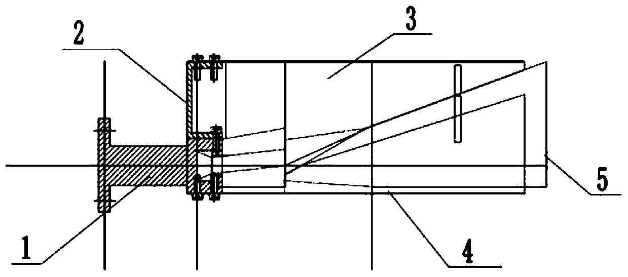
[0054] When in use, according to the service requirements of the blade, it is necessary to control the size of the ion release gap by adjusting the size of the clamping gap. When preparing a gradient layer coating that meets the erosion and fatigue performance requirements on the blade surface, use It is necessary to adjust the width of the clamping gap to 2mm, and spray a coating with a gradient layer as an example, we can follow the steps below to assemble the fixture:

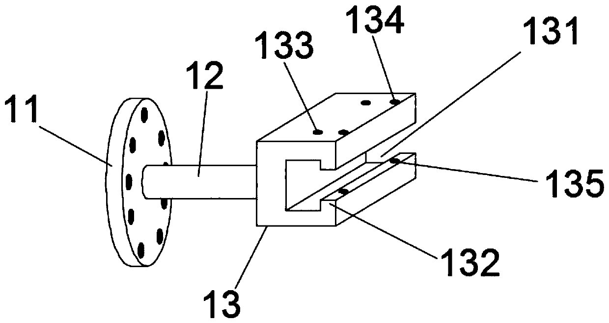
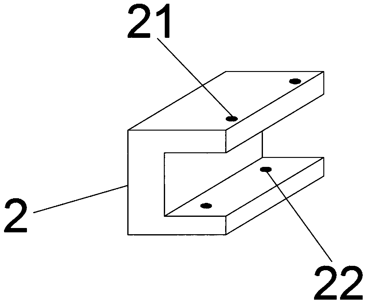
[0055] Step 1: First, use the hexagonal bolts to sequentially pass through the fifth threaded connection hole 22 and the first threaded connection hole 133 to connect the blade fixed shaft 1 to the cover plate bracket 2; then connect the blade fixed shaft 1 to the cover plate bracket 2, and connect the The tenon part of the blade (engine or turbine) that needs to be prepared with a gradient coating is clamped in the tenon part clamping groove 131. After the blade is fixed, install the lower cover plate 4 and ...

Embodiment 2

[0065] The difference from Example 1 is that in use, according to the service requirements of the blade, it is necessary to control the size of the ion release gap by adjusting the size of the clamping gap, and prepare a non-gradient blade on the surface of the blade that meets the requirements of erosion and fatigue performance. When coating the coating, we need to adjust the width of the clamping gap to 0.2mm and spray the coating without gradient layer as an example. We can assemble the fixture according to the following steps:

[0066]Step 1: First, use the hexagonal bolts to sequentially pass through the fifth threaded connection hole 22 and the first threaded connection hole 133 to connect the blade fixed shaft 1 to the cover plate bracket 2; then connect the blade fixed shaft 1 to the cover plate bracket 2, and connect the The tenon part of the blade (engine or turbine) that needs to be prepared with a gradient coating is clamped in the tenon part clamping groove 131. Af...

Embodiment 3

[0075] Different from Embodiment 2 and Embodiment 1, according to the different sizes of the blades, it is necessary to adjust the relative position of the fixed shaft 1 and the cover plate bracket 2 on the upper cover plate 3 and the lower cover plate 4 to adjust the volume of the blade installation cavity Size, so that the parts of blades of different volumes that need to be sprayed can extend out of the clamping gap, so as to meet the needs of spraying on the surface of the blades. When preparing a gradient coating that meets the requirements of erosion and fatigue performance, this embodiment adopts This is achieved in the following ways:

[0076] We are also provided with a first sliding fixing groove 312 on the upper top plate 31. The first sliding fixing groove 312 is used in conjunction with the fourth threaded connection hole 21 and the hexagon bolt. When in use, pass the hexagon bolt through the first sliding fixing groove in turn 312 and the fourth threaded connecti...


PUM

PropertyMeasurementUnit
thicknessaaaaaaaaaa

Abstract

The invention discloses a clamp for preparing a coating on the selective surface area of a blade and a preparation method of the coating. The clamp comprises a blade fixing shaft, a cover plate bracket, an upper cover plate and a lower cover plate, wherein the blade fixing shaft is connected with the cover plate bracket, the upper cover plate is mounted on the upper end face of the cover plate bracket, the lower cover plate is mounted on the lower end face of the blade fixing shaft, and the upper cover plate and the lower cover plate are connected in a staggered clamping manner. The blade canbe clamped and fixed by using the clamp when a hard coating is sprayed on an engine blade or a turbine blade, the coating meeting the requirements of erosion and fatigue performance is prepared on thesurface of the blade by using a zonal coating process, the requirement for locally spraying the hard coating on the engine blade or the turbine blade is met, the erosion damage of the surface of theblade is reduced, and the fatigue strength of the blade is ensured. The clamp has the advantages of being simple in structure, convenient to use and reasonable in design.

Description

technical field [0001] The invention belongs to the technical field of advanced manufacturing of aero-engines, and in particular relates to a jig for preparing a coating on a blade surface by selecting a region and a preparation method of the coating. Background technique [0002] When fighter jets and helicopters fly, take off and land in the desert, the dust and sand particles in the air will have a serious impact on the blades of the engine, especially a certain area on both sides of the blade tip, under the action of high-speed airflow. In severe cases, it will lead to the shedding of the area near the tip of the blade, which will have a greater impact on the performance of the engine from the structure; introducing a hard coating on the surface of the blade can significantly improve the erosion resistance of the blade, but the hard coating The introduction of will lead to the reduction of blade fatigue strength; [0003] Experimental studies and numerical simulations s...

Claims


Application Information

Patent Timeline
Patent Type & Authority Applications(China)
IPC IPC(8): C23C14/50C23C14/02C23C14/16C23C14/48C23C14/34C23C14/06C23C14/32
CPCC23C14/50C23C14/021C23C14/165C23C14/16C23C14/48C23C14/3407C23C14/325C23C14/0641C23C14/0021
Inventor 何光宇张兆路杨竹芳陈皎韩霄
Owner AIR FORCE UNIV PLA
Why Eureka
Try Eureka