Bridge water dripping groove structure

A technology of dripping tanks and structures, applied in bridges, bridge construction, bridge parts, etc., can solve problems such as deterioration, affecting the durability of bridge main girders, side beams, clean and beautiful appearance, concrete corrosion, etc., to achieve excellent weather resistance and increase the partition effect , good water resistance effect

Pending Publication Date: 2020-08-25
HENAN PROVINCIAL COMM PLANNING & DESIGN INST CO LTD
View PDF8 Cites 1 Cited by
  • Summary
  • Abstract
  • Description
  • Claims
  • Application Information

AI Technical Summary

Problems solved by technology

At present, the dripping tanks of bridges are mostly cut from the middle of the steel pipe when casting the edge beam, and welded at the end of the flange plate at the distance from the steel mold. This method does not play a good partition role in practice, resulting in Concrete corrosion and deterioration of bridge side beams under long-term rain erosion have seriously affected the durability of bridge main girders and the neat and beautiful appearance of side beams

Method used


Image

  • Bridge water dripping groove structure
  • Bridge water dripping groove structure

Examples


Embodiment 1

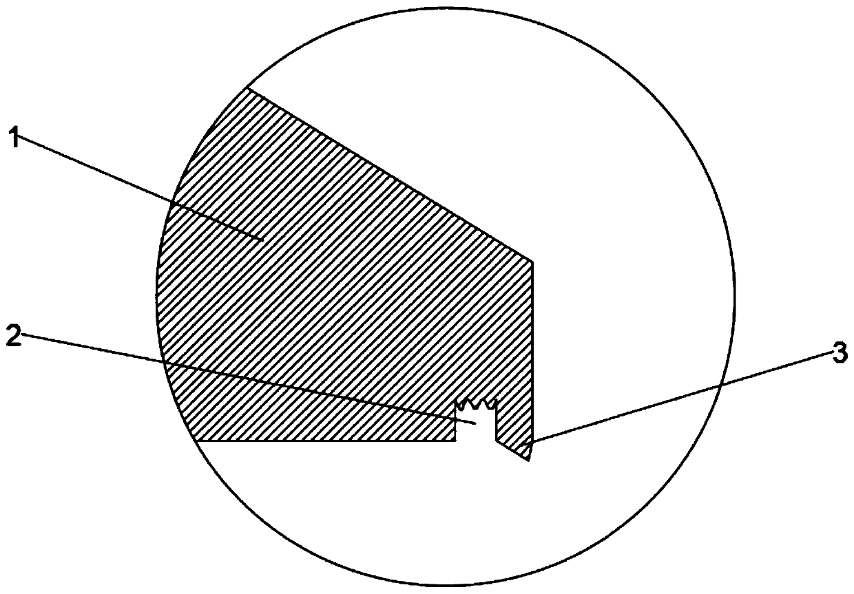
[0045] A bridge drip tank construction such as figure 1 As shown, it includes a side beam flange plate 1 and a drip groove 2, and the drip groove 2 is arranged at a position close to the lower edge end of the side beam flange plate 1; the shape of the drip groove 2 is a U-shaped opening downward; the Between the drip groove 2 and the end of the lower edge of the side sill flange 1 is formed a sharp-edged edge guard 3 protruding downwards, which is thin on the outside and thick on the inside.

[0046] The end of the drip groove 2 away from the opening is configured as a corrugated structure.

[0047] The inner surface of the drip tank 2 and the surface of the edge protection 3 are all coated with a polymer cement waterproof and anti-corrosion coating.

[0048] The polymer cement waterproof and anticorrosion coating is composed of a solid component and a liquid component;

[0049] The liquid component consists of the following components in parts by weight:

[0050] 55 parts ...

Embodiment 2

[0078] A bridge drip tank construction such as figure 1 As shown, it includes a side beam flange plate 1 and a drip groove 2, and the drip groove 2 is arranged at a position close to the lower edge end of the side beam flange plate 1; the shape of the drip groove 2 is a U-shaped opening downward; the Between the drip groove 2 and the end of the lower edge of the side sill flange 1 is formed a sharp-edged edge guard 3 protruding downwards, which is thin on the outside and thick on the inside.

[0079] The end of the drip groove 2 away from the opening is configured as a corrugated structure.

[0080] The inner surface of the drip tank 2 and the surface of the edge protection 3 are all coated with a polymer cement waterproof and anti-corrosion coating.

[0081] The polymer cement waterproof and anticorrosion coating is composed of a solid component and a liquid component;

[0082] The liquid component consists of the following components in parts by weight:

[0083] 45 parts ...

Embodiment 3

[0111] A bridge drip tank construction such as figure 1 As shown, it includes a side beam flange plate 1 and a drip groove 2, and the drip groove 2 is arranged at a position close to the lower edge end of the side beam flange plate 1; the shape of the drip groove 2 is a U-shaped opening downward; the Between the drip groove 2 and the end of the lower edge of the side sill flange 1 is formed a sharp-edged edge guard 3 protruding downwards, which is thin on the outside and thick on the inside.

[0112] The end of the drip groove 2 away from the opening is configured as a corrugated structure.

[0113] The inner surface of the drip tank 2 and the surface of the edge protection 3 are all coated with a polymer cement waterproof and anti-corrosion coating.

[0114] The polymer cement waterproof and anticorrosion coating is composed of a solid component and a liquid component;

[0115] The liquid component consists of the following components in parts by weight:

[0116] 65 parts ...


PUM


Abstract

The invention relates to the field of bridge structures, and particularly relates to a bridge water dripping groove structure which comprises an edge beam flange plate and a water dripping groove. Thewater dripping groove is arranged in a position close to an end of a lower edge of the edge beam flange plate. The water dripping groove is in a U shape with a downward opening. And a sharp corner type protective edge protruding downwards is formed between the water dripping groove and an end part of the lower edge of the edge beam flange plate. The water dripping groove structure solves problemsthat an existing water dripping groove structure cannot play a good role in separation, concrete corrosion and degradation of a bridge edge beam occur under long-term rainwater erosion, and durability of a bridge main beam and tidiness and attractiveness of an appearance of the edge beam are seriously affected. The water dripping groove structure has advantages of double partitions, a simple structure and convenience in construction.

Description

technical field [0001] The invention relates to the field of bridge structures, in particular to a bridge drip tank structure. Background technique [0002] With the rapid development of cities, urban overpasses and viaducts gradually appear on the streets of various large and medium-sized cities and become a beautiful landscape. The end is provided with intercepting grooves, its main function is to cut off the rainwater flowing down along the flange plate, make it drip vertically, and prevent the rainwater from eroding the entire facade. At present, the dripping tanks of bridges are mostly cut from the middle of the steel pipe when casting the edge beam, and welded at the end of the flange plate at the distance from the steel mold. This method does not play a good partition role in practice, resulting in Concrete corrosion and deterioration of bridge side beams under long-term rain erosion have seriously affected the durability of bridge girders and the appearance of side ...

Claims


Application Information

Patent Timeline
IPC IPC(8): E01D19/08C09D133/00C09D123/22C09D5/08C09D7/65C09D7/63C09D7/61C08F8/34C08F265/00
CPCC08F8/34C08K2003/265C08L2205/03C09D5/08C09D133/00C09D7/61C09D7/63C09D7/65E01D19/086C08L23/22C08L1/286C08K13/02C08K3/36C08K3/34C08K3/26C08K5/0091C08K5/17C08K5/5425C08K5/101C08K5/11C08F265/00
Inventor 张毅王鹏飞韩道录邓稳平王珂冯小青晁代飞郭红涛王庆丰申成岳
Owner HENAN PROVINCIAL COMM PLANNING & DESIGN INST CO LTD
Why Eureka
Try Eureka