
Automatic hanging type drying and cooling device

A cooling device, hanging technology, applied in the field of mechanical processing, can solve the problems of insufficient product drying, affecting product cleanliness, large floor space, etc., to avoid the outflow of unqualified products, avoid cleanliness problems, and save space. effect of space

Pending Publication Date: 2020-08-25
PINGYUAN FILTER
View PDF0 Cites 8 Cited by
  • Summary
  • Abstract
  • Description
  • Claims
  • Application Information

AI Technical Summary

Problems solved by technology

This drying method has the following defects: Since the cooling is cooled in the atmosphere, it is difficult to control the cooling time; the floor area is large, and a special cooling area needs to be added; there is no recycling device for the pallet, and it is necessary to increase the delivery by a special person, which reduces the work. efficiency, and increased labor costs
The existing drying method chain plate oven also has insufficient drying of the product, which affects the cleanliness of the product, which makes the engine fuel injector blocked when the product is used in the fuel system of a motor vehicle, resulting in quality accidents

Method used


Image

  • Automatic hanging type drying and cooling device
  • Automatic hanging type drying and cooling device
  • Automatic hanging type drying and cooling device

Examples


Embodiment Construction

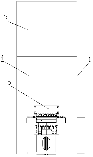
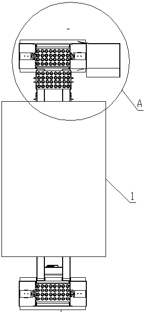
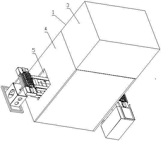
[0044] Such as Figure 1 to Figure 8 As shown, the automatic hanging drying and cooling device of the present invention includes a drying box 1 and several trays 2, and the drying box 1 is divided up and down with a drying chamber 3 positioned at the top and a cooling chamber 4 positioned at the bottom; the cooling chamber The lower part of 4 is provided with a left opening 5 and a right opening 6 opposite to each other;

[0045] The left opening 5 is provided with a feed conveyor belt mechanism 7 arranged horizontally, and the feed conveyor belt mechanism 7 is used to send the product to be dried from the outside of the drying box 1 into the drying box 1;

[0046] The right opening 6 is provided with a horizontally arranged discharge conveyor belt mechanism 8, which is used to send the dried product out of the drying box 1; the feed conveyor belt mechanism 7 and the discharge conveyor belt mechanism 8, the feeding direction is from left to right;

[0047] The structure of f...


PUM


Abstract

The invention discloses an automatic hanging type drying and cooling device. The automatic hanging type drying and cooling device comprises a drying box and a plurality of trays, wherein the interiorof the drying box is divided into a drying chamber at the upper portion and a cooling chamber at the lower portion; a left opening and a right opening are respectively and oppositely formed in the left lower portion and the right lower portion of the cooling chamber; a feeding conveyor belt mechanism is arranged at the left opening; a discharging conveyor belt mechanism is arranged at the right opening; a conveying chain mechanism is arranged in the drying box; the trays comprise horizontal carrying plates and vertical hanging plates; hook holes matched with hook parts of hooks are formed in the tops of the vertical hanging plates; a conveyor belt of the feeding conveyor belt mechanism is positioned at the bottom of the ascending part of a conveying chain; and a conveyor belt of the discharging conveyor belt mechanism is positioned at the bottom of the descending part of the conveying chain. A cooling area does not need to occupy a separate space, so that the occupied space is greatlysaved; the cooling area is changed from a structure in a prior open environment to the cooling chamber enclosed in the drying box, so that the temperature in the cooling chamber is convenient to adjust and control; and the automatic hanging type drying and cooling device saves manpower and improves working efficiency.

Description

technical field [0001] The invention relates to the technical field of mechanical processing, in particular to a product drying and cooling mechanism. Background technique [0002] In the field of mechanical processing, some products (such as the pressure filter used in the motor vehicle gearbox targeted by the present invention) need to be dried in a chain plate oven, and cooled in the atmosphere after drying. This drying method has the following defects: Since the cooling is cooled in the atmosphere, it is difficult to control the cooling time; the floor area is large, and a special cooling area needs to be added; there is no recycling device for the pallet, and it is necessary to increase the delivery by a special person, which reduces the work. efficiency and increase labor costs. The existing drying method chain plate oven also has insufficient drying of the product, which affects the cleanliness of the product. This makes the engine fuel injector blocked when the prod...

Claims


Application Information

Patent Timeline
IPC IPC(8): F26B15/08F26B25/00F26B25/02
CPCF26B15/08F26B25/00F26B25/003F26B25/02
Inventor 汪先磊王营军于洋
Owner PINGYUAN FILTER
Learn More