Peppermint raw material screening device for peppermint oil manufacturing

A screening device, the technology of peppermint oil, applied in the direction of sieve, solid separation, grille, etc., can solve the problems of inability to adjust the thickness of the scraping layer according to the actual needs, clogging of the screen, inconvenient cleaning, etc., to achieve good protection effect and convenient The effect of screening and avoiding wear

Active Publication Date: 2020-08-28
安徽华馨生物科技有限公司
7 Cites 5 Cited by

AI-Extracted Technical Summary

Problems solved by technology

[0006] Aiming at the deficiencies of the prior art, the present invention provides a mint raw material screening device for peppermint oil production, which overcomes the deficiencies of the prior art, has a simple structural design, and effect...

Method used

In the present embodiment, as shown in Figure 2, described spring 16 and scraper 12 are positioned at the same side outside of fixed plate 9, and described fixed plate 9 is positioned at the top of screen cloth 33, and the restoring for...

Abstract

The invention relates to the technical field of peppermint oil manufacturing, in particular to a peppermint raw material screening device for peppermint oil manufacturing. The peppermint raw materialscreening device comprises a screening barrel, wherein a barrel cover is arranged at the top end of the screening barrel, a feeding hopper is arranged on one side of the top end of the barrel cover, amounting rod is arranged in the center of the bottom end of the barrel cover, a connecting plate is arranged on one side of the mounting rod, an electric push rod is arranged on one side of the bottom end of the connecting plate, a connecting rod is mounted at the output end of the electric push rod, a clamping plate is arranged at the bottom end of the connecting rod, and the clamping plate is of an inverted-concave structure. The defects in the prior art are overcome, bristles are arranged at the bottom of the vertical plate, when a screen is blocked, the vertical plate is driven by the electric push rod to be pressed downwards until the bristles make full contact with the surface of the screen, the screen rotates, the bristles can sweep the screen, and the situations that the screen isblocked and the bristles are lifted up to be separated from the screen after the screen is dredged can be effectively avoided, so that blockage of the screen is conveniently treated.

Application Domain

Technology Topic

PEPERMINT OILEngineering +3

Image

  • Peppermint raw material screening device for peppermint oil manufacturing
  • Peppermint raw material screening device for peppermint oil manufacturing
  • Peppermint raw material screening device for peppermint oil manufacturing

Examples

  • Experimental program(1)

Example Embodiment

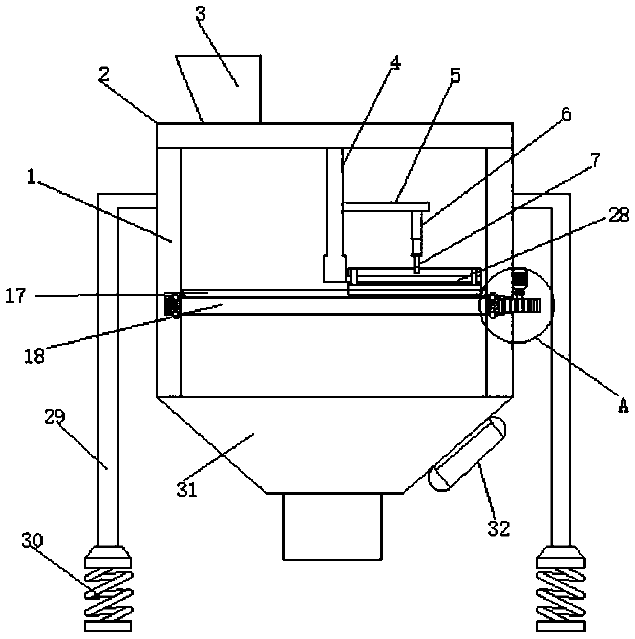
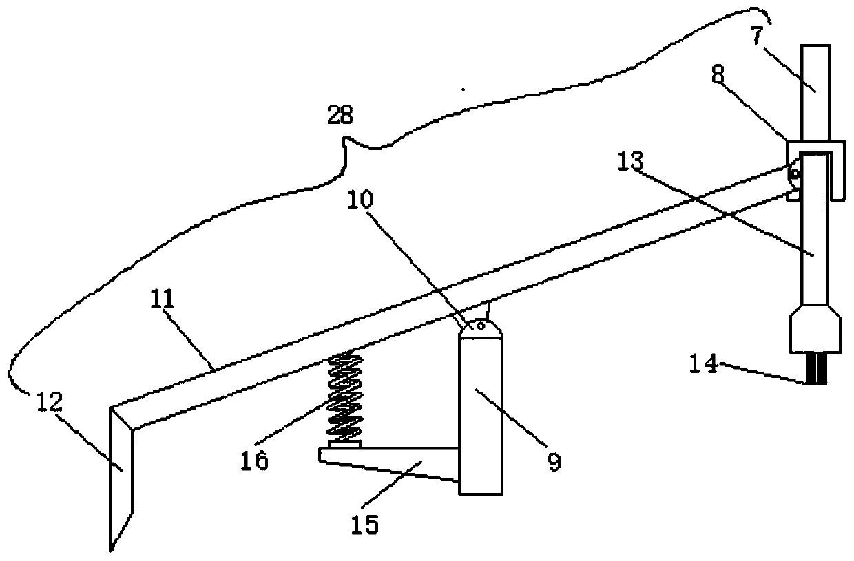
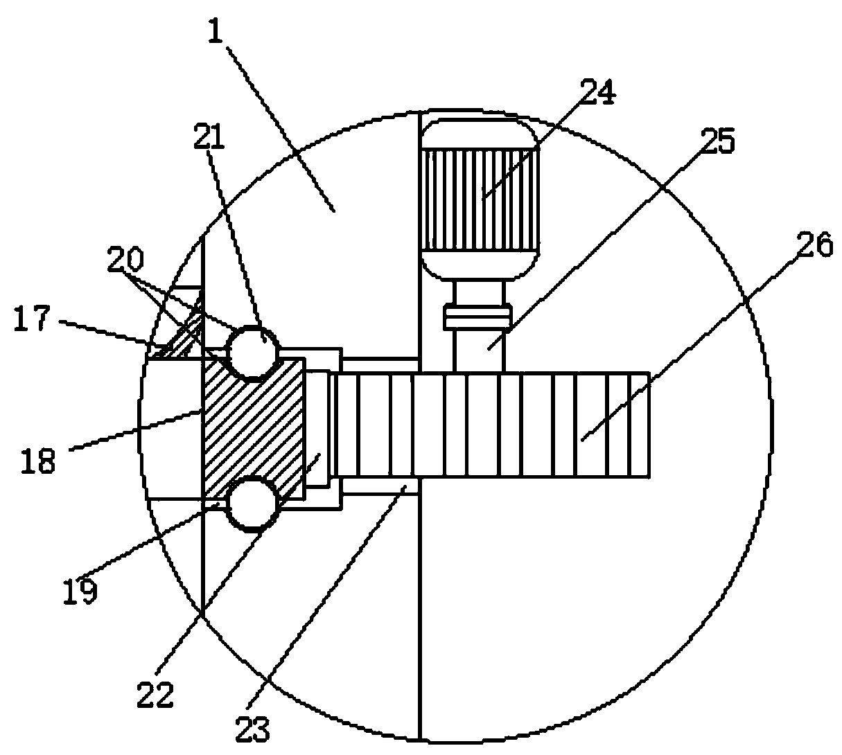
[0029] Attached below Figure 1-4 The present invention is further described with examples:
[0030] A peppermint raw material screening device for producing peppermint oil, comprising a screening barrel 1, the top of the screening barrel 1 is provided with a barrel cover 2, the top side of the barrel cover 2 is provided with a feeding hopper 3, and the feeding hopper 3 is used for feeding , a mounting rod 4 is provided at the center of the bottom end of the barrel cover 2, a connecting plate 5 is provided on one side of the mounting rod 4, and an electric push rod 6 is provided on one side of the bottom end of the connecting plate 5. The output end of the push rod 6 is provided with a connecting rod 7, the bottom end of the connecting rod 7 is provided with a clamping plate 8, the clamping plate 8 is an inverted concave structure, and the bottom end of one side of the installation rod 4 is provided with a spreader plate 8. The paving mechanism 28 includes a fixed plate 9, and both sides of the top of the fixed plate 9 are provided with a hinged seat 10, and the fixed plate 9 is movably connected with a swing rod 11 through the hinged seat 10. A scraper 12 and a vertical plate 13 are respectively provided on the outside of both sides of the plate 9, the top of the scraper 12 is connected with one end of the swing rod 11, and the other end of the swing rod 11 is hinged with the top of the side wall of the vertical plate 13, so The clamping plate 8 is clamped on the top of the vertical plate 13, the bottom end of the vertical plate 13 is provided with bristles 14, the bottom end of the side wall of the fixed plate 9 is provided with a bottom plate 15, and the top end of the bottom plate 15 is provided with a bottom plate 15. A spring 16 corresponding to the swing rod 11 is provided, and the top end of the spring 16 is hinged with the bottom end of the swing rod 11, an annular groove 19 is provided on the circumferential inner wall of the screening barrel 1, and an annular frame 18 is provided inside the screening barrel 1, The annular frame 18 is slidably connected to the inner wall of the annular groove 19 , the inside of the annular frame 18 is provided with a screen 33 , which is used to screen the raw materials, and the outer circumferential wall of the annular frame 18 is provided with external teeth 22 , the outer wall of one side of the screening barrel 1 is provided with a communication groove 23, the outer wall of one side of the screening barrel 1 is installed with a driving motor 24, and the end of the output shaft of the driving motor 24 is installed with a rotating rod 25. The bottom end of the rod 25 is provided with a driving gear 26, the driving gear 26 meshes with the external teeth 22 through the communication groove 23, and is convenient to drive the ring frame 18 to rotate, thereby rotating with the screen 33 to realize the spreading of raw materials.
[0031] In this embodiment, as Figure 1-2 As shown, the connecting plate 5 and the fixing plate 9 are vertically arranged with the mounting rod 4, and the connecting plate 5 is located directly above the fixing plate 9, which is convenient for the distance between the scraper 12, the vertical plate 13 and the screen 33, The function of realizing the spreading of raw materials and the function of cleaning the screen 33 is switched.
[0032] In this embodiment, as figure 2 As shown, the spring 16 and the scraper 12 are located outside the same side of the fixed plate 9, and the fixed plate 9 is located above the screen 33, under the action of the restoring force of the spring 16, it is convenient to reset the pendulum rod 11.
[0033] In this embodiment, as figure 1 and 3 As shown, a rubber ring 17 is provided at the top edge of the annular frame 18 to prevent leakage of raw materials.
[0034] In this embodiment, as figure 1 and 3 As shown, the top and bottom ends of the annular frame 18, the groove top and the groove top of the annular groove 19 are provided with ball grooves 20, and the ball grooves 20 are provided with balls 21, so that the annular frame 18 can be stably in the The interior of the screening bucket 1 is rotated.
[0035] In this embodiment, as figure 1 As shown, the outer walls on both sides of the screening bucket 1 are provided with support frames 29 , and the bottom ends of the support frames 29 are provided with shock-absorbing seats 30 .
[0036] In this embodiment, as figure 1 As shown, the bottom end of the screening bucket 1 is provided with a lower hopper 31 , and a vibration motor 32 is arranged on the outer side wall of the lower hopper 31 .
[0037] In this embodiment, as figure 1 As shown, the communication groove 23 communicates with the annular groove 19 .
[0038]The working principle of the present invention: by starting the driving motor 24 to rotate with the rotating rod 25, the rotating rod 25 rotates with the driving gear 26, the driving gear 26 rotates with the ring frame 18 through the external teeth 22, when the raw material falls on the screen 33 After being installed, the screen 33 rotates at the bottom of the scraper 12 with the annular frame 18, and the scraper 12 can spread the raw materials on the screen 18, so as to facilitate the screen 18 to screen the raw materials. Driven by the output end, the connecting rod 7 can move up and down, and the connecting rod 7 moves synchronously with the clamping plate 7. When the connecting rod 7 is pressed down, the vertical plate 13 can be pressed down, and the vertical plate 13 swings with the swing rod 11, so that The end of the swing rod 11 with the scraper 13 can be lifted up and down. At this time, the spring 16 is in a stretched state, so that the distance between the scraper 13 and the screen 33 can be easily changed, so as to meet the needs of different paving thicknesses and facilitate the distribution of raw materials. For screening, by arranging bristles 14 at the bottom of the vertical plate 13, when the screen 33 is blocked, driven by the electric push rod 6, the vertical plate 13 is pressed down until the bristles 14 are in full contact with the surface of the screen 33, When the screen 33 rotates, the bristles 14 can clean the screen, which can effectively avoid the blockage of the screen 33. After the screen 33 is cleared, the bristles 14 are lifted up and separated from the screen 33, so as to facilitate the treatment of the blockage of the screen 33. .
[0039] The embodiment of the present invention announces the preferred embodiment, but is not limited to this, those of ordinary skill in the art can easily understand the spirit of the present invention according to the above-mentioned embodiment, and make different extensions and changes, However, as long as they do not depart from the spirit of the present invention, they are all within the protection scope of the present invention.

PUM

no PUM

Description & Claims & Application Information

We can also present the details of the Description, Claims and Application information to help users get a comprehensive understanding of the technical details of the patent, such as background art, summary of invention, brief description of drawings, description of embodiments, and other original content. On the other hand, users can also determine the specific scope of protection of the technology through the list of claims; as well as understand the changes in the life cycle of the technology with the presentation of the patent timeline. Login to view more.

Similar technology patents

Classification and recommendation of technical efficacy words

  • Easy to sieve
  • Simple structural design

Kitchen garbage treatment device

ActiveCN107199094AUniform sizeEasy to sieveSievingScreeningMechanical engineeringFood waste
Owner:镇江康乐服务机器人有限公司

Continuous online countercurrent extraction device for plants

InactiveCN109481956AEasy to sieveEasy to cleanCounter-current extractionSolid solvent extractionGastric tube feedingFeeding tube
Owner:YUNNAN AGRICULTURAL UNIVERSITY +1

Titanium alloy powder screening device

Owner:JIANGSU VILORY ADVANCED MATERIALS TECH CO LTD

A graphic OSD controller integrated into video processing chip

InactiveCN101150682AReduce storage space requirementsSimple structural designTelevision system detailsColor television detailsWork patternBitmap
Owner:XI AN JIAOTONG UNIV
Why Eureka
Try Eureka