Metal plate stamping die

A stamping die and sheet metal technology, applied in the direction of forming tools, manufacturing tools, metal processing equipment, etc., can solve the problems that the edges of sheet metal parts are prone to bending, metal shavings cannot be cleaned in time, and affect the precision of sheet metal stamping, etc., to achieve Effects of improving fixing strength, preventing displacement and swing, and improving quality

Inactive Publication Date: 2020-08-28
胡远芳
View PDF0 Cites 4 Cited by
  • Summary
  • Abstract
  • Description
  • Claims
  • Application Information

AI Technical Summary

Problems solved by technology

[0004] In order to make up for the deficiencies of the existing technology, the edge of the sheet metal part is easy to bend, so that the sheet metal part is easy to cause inaccurate positioning during stamping, affecting the size of the product, and also causing waste of sheet metal part materials. A large amount of metal chips produced during the stamping process cannot be cleaned in time, which seriously affects the precision of sheet metal stamping, and different shapes of sheet metal require different fixtures for clamping. It is too cumbersome to replace fixtures during the stamping process of different shapes of sheet metal, which wastes manpower and material resources. The problem of low sheet metal stamping efficiency, a sheet metal stamping die proposed by the present invention

Method used


Image

  • Metal plate stamping die
  • Metal plate stamping die
  • Metal plate stamping die

Examples


Embodiment approach

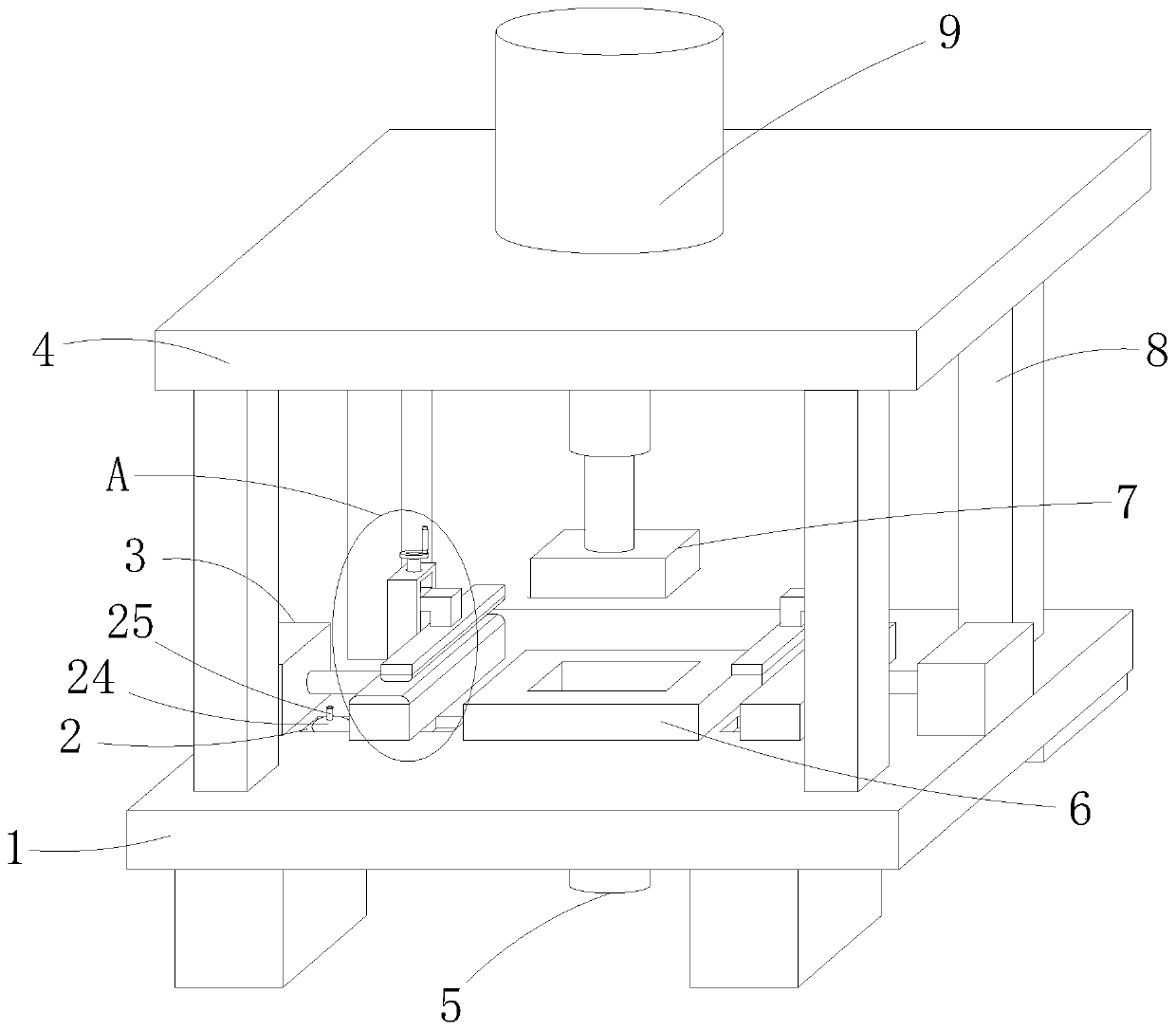
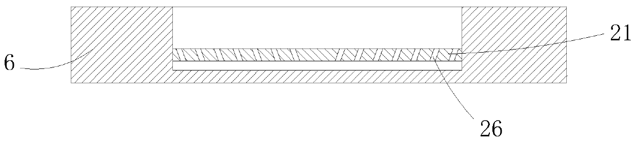
[0023] As an embodiment of the present invention, a hydraulic cylinder 2 5 is installed on the lower surface of the lower template 1, the hydraulic cylinder 2 5 is electrically connected to the controller, and the output end of the hydraulic cylinder 2 5 runs through the lower surface of the lower template 1 and the The lower surface of the die 6 extends into the cavity of the die 6 and is fixedly connected with a discharge plate 21; during work, after the sheet metal stamping is completed, the controller controls the hydraulic cylinder 25 to stretch out to make the discharge plate 21 and the concave The die 6 slides out, so that the metal scraps falling in the die 6 during the stamping process of the sheet metal parts are cleaned out of the die 6, preventing the excessive accumulation of metal scraps in the die 6 and affecting the stamping of the sheet metal parts, and the metal scraps Cleaning is convenient and quick, saving manpower and material resources.

[0024] As an em...


PUM


Abstract

The invention belongs to the technical field of metal plate stamping, and particularly relates to a metal plate stamping die. The metal plate stamping die comprises a lower die plate, the upper surface of the lower die plate is fixedly connected with an upper die plate through a plurality of supporting rods, and a first hydraulic cylinder is mounted on the upper surface of the upper die plate. During using, the edge of a metal plate piece is placed on supporting blocks, by rotating a lead screw, the lead screw rotates to drive a sliding block to move up and down, the sliding block moves up anddown to drive a pressing plate to move up and down through an L-shaped connecting rod, and thus the edge of the metal plate piece can be clamped and fixed to a fixing block; during stamping of the metal plate piece, through clamping limiting of the pressing plate and the supporting blocks, the edge of the metal plate piece is prevented from being bent during stamping, thus positioning is accurateduring stamping, thus the quality of stamping production of the metal plate piece is improved, and material waste of the metal plate piece is also avoided; and by starting an electric push rod, the distance between the two supporting blocks can be adjusted, so that metal plate pieces with different widths are used, and the applicability of the metal plate stamping die is improved.

Description

technical field [0001] The invention belongs to the technical field of sheet metal stamping, in particular to a sheet metal stamping die. Background technique [0002] Sheet metal has the characteristics of light weight, high strength, electrical conductivity (can be used for electromagnetic shielding), low cost, and good mass production performance. It has been widely used in electronic appliances, communications, automobile industry, medical equipment and other fields, such as in Sheet metal is an essential part of computer cases, mobile phones, and MP3 players. Sheet metal is a comprehensive cold working process for thin metal sheets (usually below 6mm), including shearing, punching / cutting / compositing, folding, riveting, splicing, forming (such as car body), etc. Its notable feature is that the thickness of the same part is consistent . [0003] During the blanking process of the existing sheet metal stamping die, the edge of the sheet metal part is prone to bending du...

Claims


Application Information

Patent Timeline
Patent Type & Authority Applications(China)
IPC IPC(8): B21D37/12B21D55/00B21D22/02B21D43/00B08B1/00B08B5/02
CPCB08B1/00B08B5/02B21D22/02B21D37/12B21D43/003B21D55/00
Inventor 不公告发明人
Owner 胡远芳
Why Eureka
Try Eureka