Mass concrete cooling device and using method

A technology of mass concrete and cooling device, applied in infrastructure engineering, architecture, building construction, etc., can solve problems such as loss of life and property, cracking of concrete, affecting the safe use of structures, etc., to improve cooling efficiency and ensure heat absorption. Ability, good cooling effect

Active Publication Date: 2020-08-28
ANYANG INST OF TECH
View PDF4 Cites 2 Cited by
  • Summary
  • Abstract
  • Description
  • Claims
  • Application Information

AI Technical Summary

Problems solved by technology

After the mass concrete is poured, a large amount of heat of hydration will be generated during the setting and hardening process. If the heat cannot be released in time, the temperature in the core area of ​​the concrete will be too high, the temperature difference between the inside and the outside will be large, and large stress will be generated, resulting in cracking of the concrete. , affect the safe use of the structure, and even lead to engineering accidents, causing huge losses to people's lives and property. Therefore, it is necessary to control the temperature of concrete during construction for mass concrete construction.
At present, the technology of embedding condenser pipes in concrete and passing water to realize cooling and cooling of large-volume concrete is often used in engineering. However, from the perspective of a large number of implementation projects, the cooling effect is not good, the efficiency is low, and the temperature and cooling cannot be accurately controlled. Liquid flow rate
[0003] In view of this, in order to effectively solve the problem of the temperature difference between the inside and outside of the large-volume concrete when it hardens, the cooling device and method are improved, so the present invention is proposed, a large-volume concrete cooling device and its use method

Method used


Image

  • Mass concrete cooling device and using method
  • Mass concrete cooling device and using method
  • Mass concrete cooling device and using method

Examples


Embodiment Construction

[0033] specific implementation plan

[0034] In order to make the purpose, technical solution and feasibility of the present invention more clear and detailed, the present invention will be described in detail below in conjunction with the accompanying drawings and embodiments. It should be understood that the specific examples described below are only used to explain the present invention, not to limit the present invention.

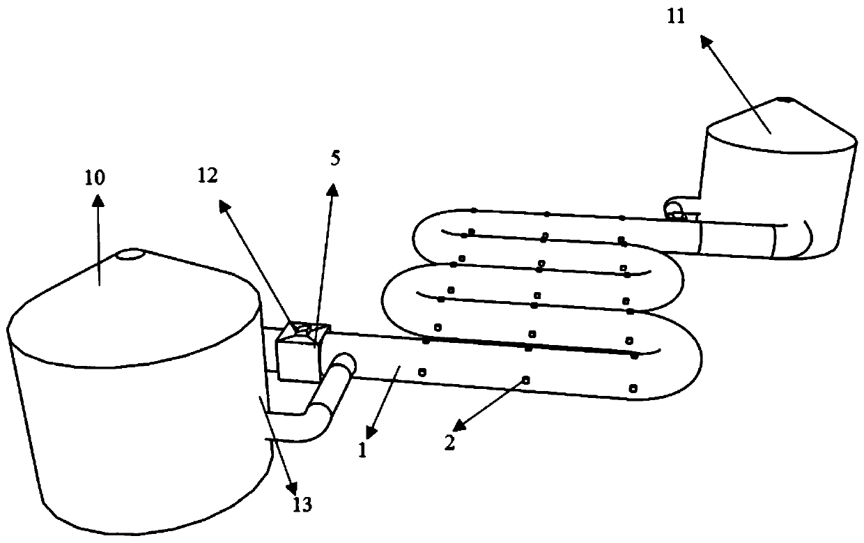
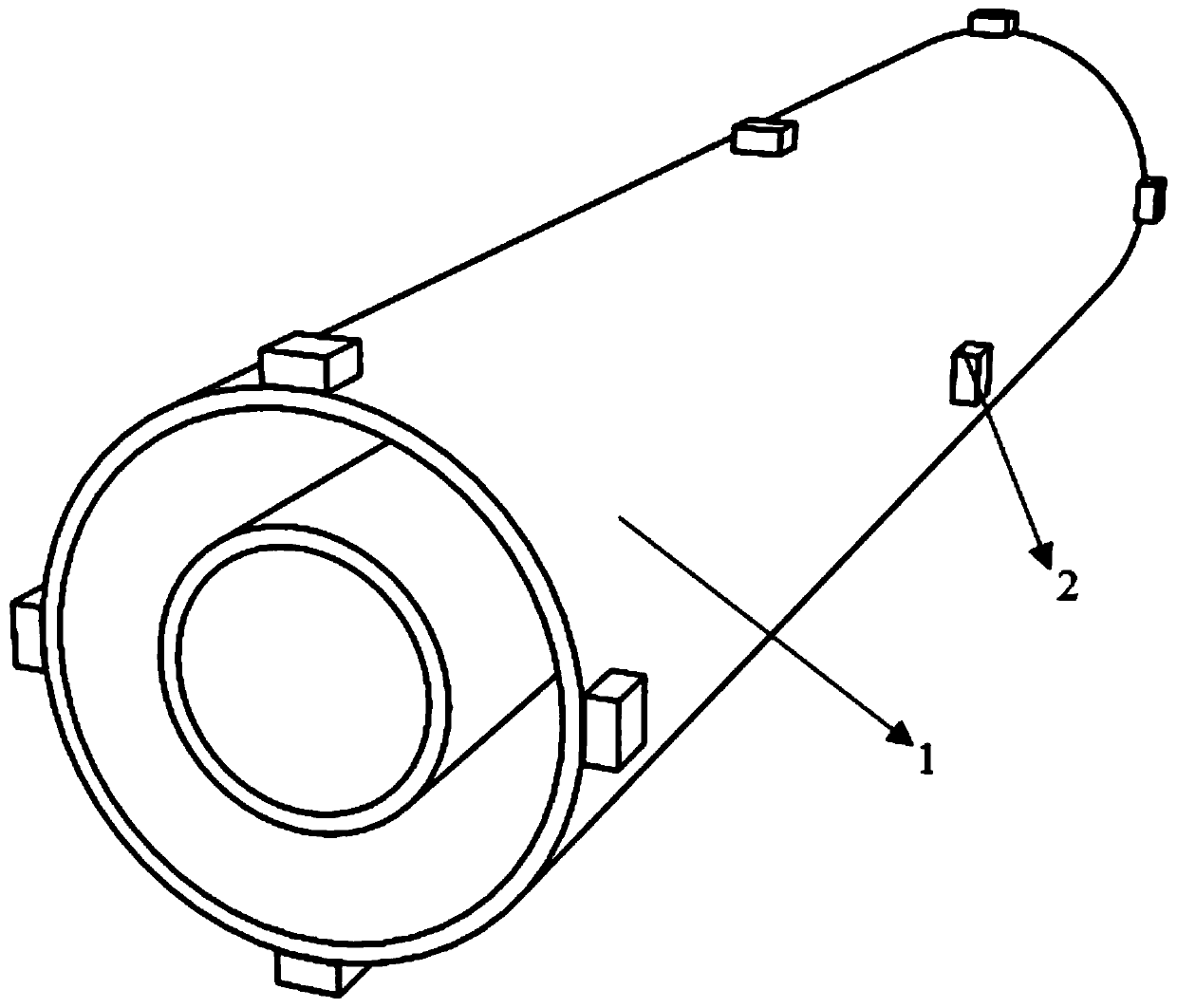
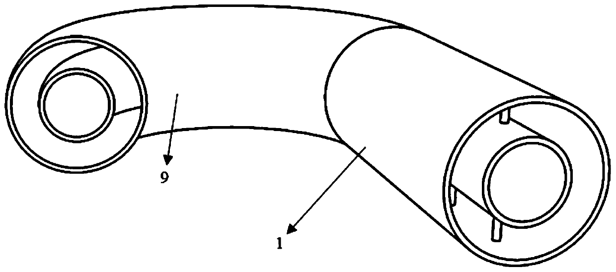
[0035] see Figure 1 to Figure 7 , a large-volume concrete cooling device, including a multi-layer cooling system arranged in the vertical direction, a No. 1 coolant storage tank 10, and a No. 2 coolant storage tank 11. The cooling system includes a pipeline system and a cooling liquid regulation system. . A data monitoring and control system, the pipeline system includes a double-layer combined pipe 1 and a double-layer rubber hose joint 9; the double-layer combined pipe 1 includes an end segment and an intermediate segment; the intermediate segment i...


PUM

PropertyMeasurementUnit
diameteraaaaaaaaaa

Abstract

The application discloses a mass concrete cooling device. The mass concrete cooling device includes multiple layers of cooling systems arranged in parallel in the top-bottom direction, a first coolantstorage tank, and a second coolant storage tank; the cooling system of each layer has the same structure, the cooling system comprises a pipe system, which includes a plurality of double-layer composite pipes, the middle sections of several double-layer composite pipes are arranged side by side and in parallel, the end parts of two adjacent double-layer composite pipes are connected through double-layer rubber hose joints, the inner and outer pipes at one end of the pipe system are respectively connected with the inlet and outlet of the first coolant storage tank, and the inner and outer pipes at the other end of the pipe system are respectively connected with the outlet and inlet of the second coolant storage tank; and a plurality of stress-temperature sensors are evenly distributed on the outer pipe walls of the double-layer composite pipes and the outer surface of concrete to detect the temperature difference between the outer pipe walls and the outer surface of the concrete, and the flow volume and flow rate of coolant in the inner and outer pipes of the double-layer composite pipes are adjusted to improve the cooling efficiency and effect of the concrete.

Description

technical field [0001] The invention belongs to the technical field of engineering construction, and in particular relates to a large-volume concrete cooling device and a use method. Background technique [0002] With the increasing demand for mass concrete in some construction projects in our country, the quality requirements of mass concrete are particularly prominent. After the mass concrete is poured, a large amount of heat of hydration will be generated during the setting and hardening process. If the heat cannot be released in time, the temperature in the core area of ​​the concrete will be too high, the temperature difference between the inside and the outside will be large, and large stress will be generated, resulting in cracking of the concrete. , affect the safe use of the structure, and even lead to engineering accidents, causing huge losses to people's lives and property. Therefore, it is necessary to control the temperature of concrete during construction for m...

Claims


Application Information

Patent Timeline
Patent Type & Authority Applications(China)
IPC IPC(8): E04G21/02E04G21/24E02D15/02C04B40/02
CPCC04B40/02E02D15/02E04G21/02E04G21/246
Inventor 刘龙徐雯涛郭欣左可魏毕迎迎王修养姜文豪王颖
Owner ANYANG INST OF TECH
Why Eureka
Try Eureka