
Large-scale multistage rocket-based combined cycle engine

A rocket-based, large-scale technology, applied in the direction of combined engines, engine components, machines/engines, etc., can solve the problems of engine structural quality, structural complexity, thermal protection, engine flow path internal resistance increase, etc.

Pending Publication Date: 2020-08-28
NORTHWESTERN POLYTECHNICAL UNIV
View PDF3 Cites 2 Cited by
  • Summary
  • Abstract
  • Description
  • Claims
  • Application Information

AI Technical Summary

Problems solved by technology

In order to solve these problems, if the traditional liquid fuel injection method is still used, due to the limitation of the fuel injection penetration depth and other problems, it is necessary to add a large number of fuel support plates and other combustion auxiliary enhancement devices, but this will lead to the structural quality of the engine. , structural complexity, difficulty in thermal protection, and the internal resistance of the engine flow path have increased significantly

Method used


Image

  • Large-scale multistage rocket-based combined cycle engine
  • Large-scale multistage rocket-based combined cycle engine
  • Large-scale multistage rocket-based combined cycle engine

Examples


Embodiment Construction

[0022] The present invention will be described in further detail below in conjunction with the accompanying drawings and specific embodiments.

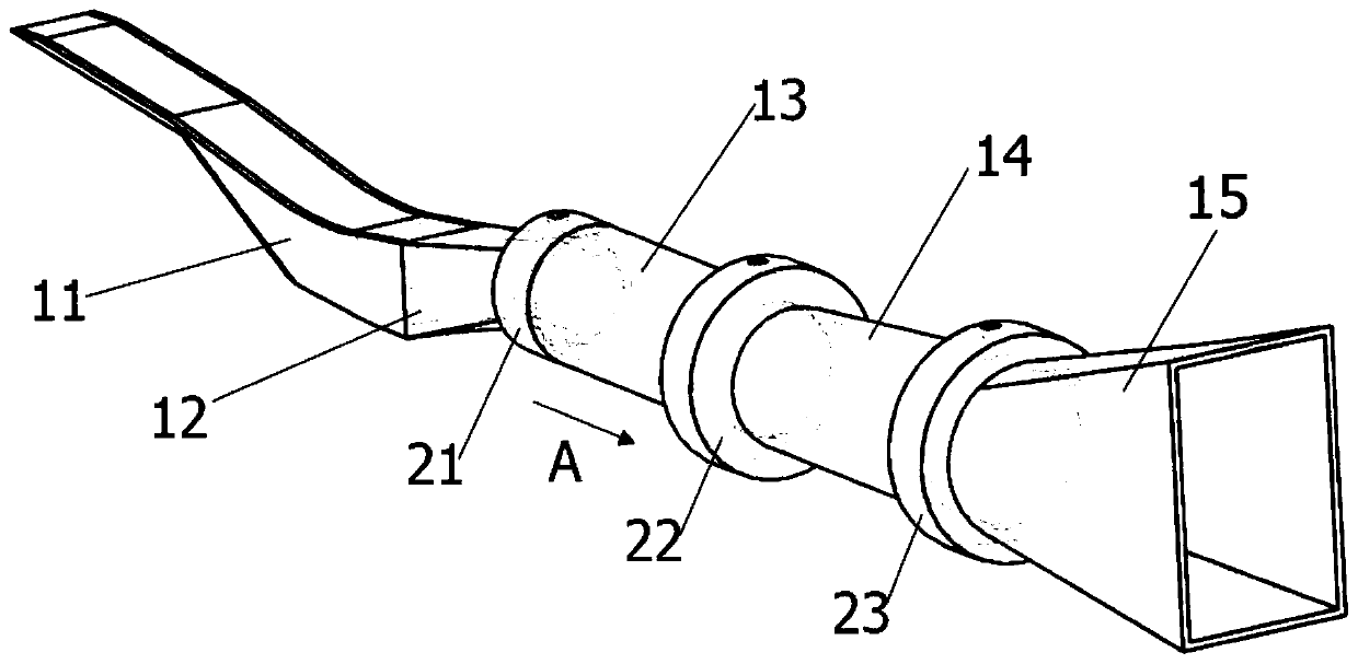
[0023] See Figure 1-3 As shown, the present invention provides a large-scale multi-stage rocket-based combined cycle engine, comprising an air inlet 11, an isolation section 12, a first-stage combustion chamber 13, a second-stage combustion chamber 14, an exhaust nozzle 15, and a first rocket unit 21 , second rocket unit 22 and third rocket unit 23 .

[0024] The intake passage 11, the isolation section 12, the first-stage combustion chamber 13, the second-stage combustion chamber 14 and the tail nozzle 15 are connected in sequence, specifically, the intake passage 11, the isolation section 12, the first-stage combustion chamber 13, The second-stage combustion chamber 14 and the tail nozzle 15 are connected by flange connection or welding. The air flow flows from the air inlet 11 through the isolation section 12, the first-stage co...


PUM

PropertyMeasurementUnit
Length dimensionaaaaaaaaaa

Abstract

The invention provides a large-scale multistage rocket-based combined cycle engine. The engine comprises an air inlet duct, an isolation section, a first-stage combustion chamber, a second-stage combustion chamber, an exhaust nozzle, a first rocket unit, a second rocket unit and a third rocket unit. Airflow flows in from the air inlet duct, passes through an isolation flow channel and the combustion chambers, and then is discharged out through the exhaust nozzle. The isolation flow channel is cylindrical, the vertical section, in the axis direction, of the isolation flow channel has the same outer diameter dimension, and the isolation flow channel is used for decelerating and boosting the airflow flowing in from the air inlet duct. The exhaust nozzle is in a flared shape in the airflow outflowing direction, and is used for increasing the flow speed of the outflowing airflow. The arranged isolation flow channel enables the air inlet duct and the combustion chambers to be stably distributed in an isolated manner, and enables the airflow to be decelerated and boosted in the isolation flow channel after the airflow passes through the air inlet duct, so that the combustion efficiency isprevented from being affected by large airflow fluctuation of the airflow in an air inlet section, and the matching stability of the air inlet duct and rocket units is improved.

Description

technical field [0001] The invention relates to the field of air-breathing combined propulsion systems, in particular to a large-scale multi-stage rocket-based combined cycle engine. Background technique [0002] The Rocket-Based Combined Cycle (RBCC) engine organically integrates a rocket engine with a high thrust-to-weight ratio and an air-breathing ramjet engine with a high specific impulse in the same flow channel, and is compatible with ejection, subcombustion, and scramjet And pure rocket mode, to achieve high-performance work in wide speed range and large airspace. How to ensure that the same engine can achieve good operation of each mode in such a wide Mach number range, as well as smooth transition between different modes, is the key to the success of the RBCC engine. Among them, the configuration and working method adopted by the RBCC engine play a decisive role. In particular, how to ensure a reasonable match between the rocket layout and the ramjet runner layou...

Claims


Application Information

Patent Timeline
IPC IPC(8): F02K7/18F02C3/14F02C7/04F02C7/042F02C9/28F02K1/78F23R3/42F23R3/28
CPCF02K7/18F02C3/14F02C7/04F02C7/042F02C9/28F02K1/78F23R3/42F23R3/28
Inventor 石磊杨一言杨雪赵国军魏祥庚秦飞何国强
Owner NORTHWESTERN POLYTECHNICAL UNIV
Learn More