Improved water chilling unit testing device with heat recovery function

A chiller and testing device technology, applied in measuring devices, testing of machines/structural components, instruments, etc., to achieve the effects of reducing operating flow and overall energy consumption, simplifying cooling schemes, and large heat transfer temperature differences

Active Publication Date: 2020-08-28
HEFEI GENERAL MACHINERY RES INST +1
View PDF16 Cites 2 Cited by
  • Summary
  • Abstract
  • Description
  • Claims
  • Application Information

AI Technical Summary

Problems solved by technology

The existing test equipment for testing chillers cannot achieve the above goals, so there is an urgent need for an improved test equipment for testing chillers with heat recovery function

Method used


Image

  • Improved water chilling unit testing device with heat recovery function
  • Improved water chilling unit testing device with heat recovery function
  • Improved water chilling unit testing device with heat recovery function

Examples


Embodiment 1

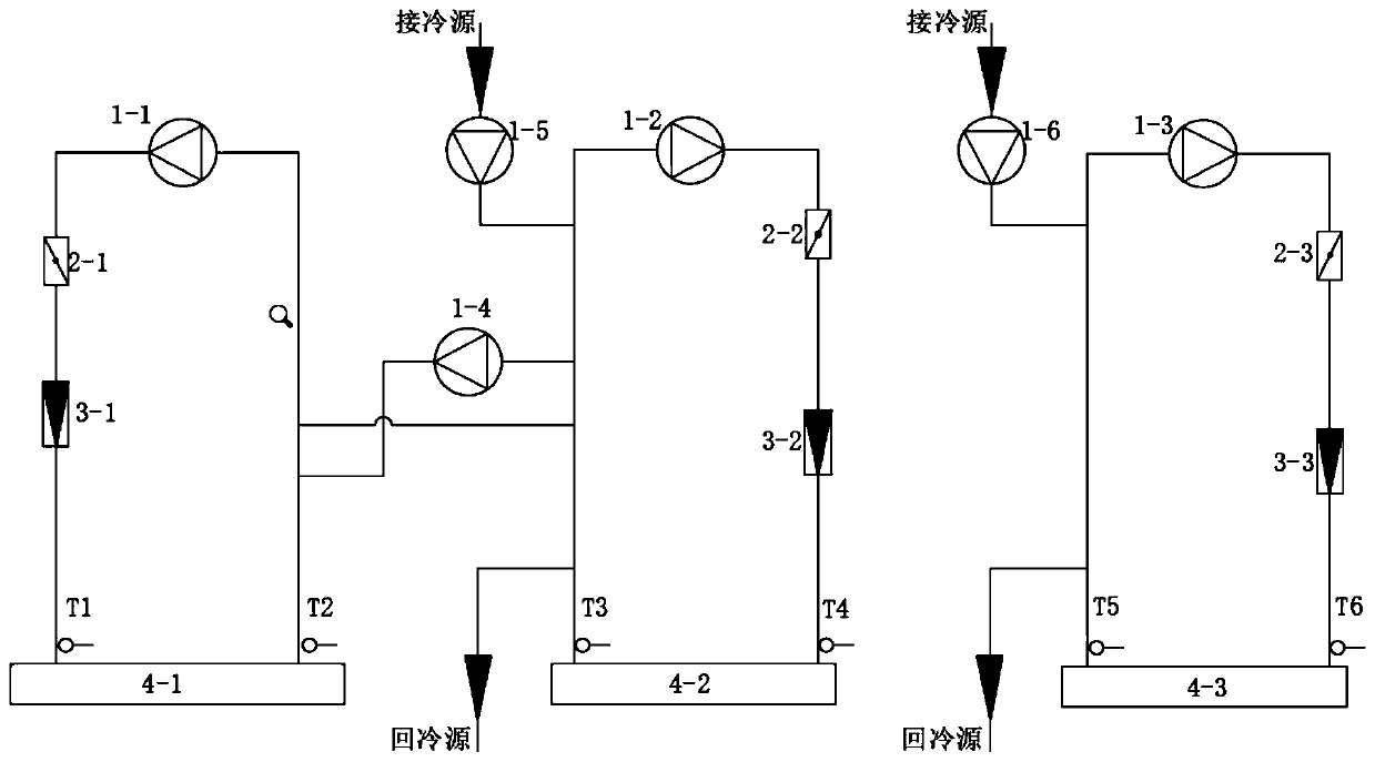
[0035] Such as figure 1 As shown, an improved test device for testing chillers with heat recovery function, including the evaporator side circulation pipeline connected to the evaporator 4-1, and the condenser side circulation pipeline connected to the condenser 4-2 . The heat recovery unit side circulation pipeline connected to the heat recovery unit 4-3, the first water conversion circulation pipeline, the second water conversion circulation pipeline, and the third water conversion circulation pipeline. The evaporator 4-1 and the circulation pipeline on the evaporator side, the condenser 4-2 and the circulation pipeline on the condenser side, the circulation pipeline on the heat recovery unit and the heat recovery unit 4-3 all form a closed cycle. The circulation pipeline on the evaporator side communicates with the circulation pipeline on the condenser side through the first water exchange circulation pipeline, the heat recovery side circulation pipeline communicates with t...

Embodiment 2

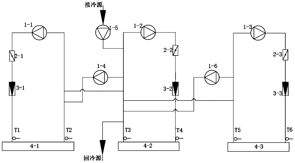
[0046] Such as figure 2 As shown, an improved test device for testing chillers with heat recovery function, including the evaporator side circulation pipeline connected to the evaporator 4-1, and the condenser side circulation pipeline connected to the condenser 4-2 . The heat recovery unit side circulation pipeline connected to the heat recovery unit 4-3, the first water conversion circulation pipeline, the second water conversion circulation pipeline, and the third water conversion circulation pipeline. The evaporator 4-1 and the circulation pipeline on the evaporator side, the condenser 4-2 and the circulation pipeline on the condenser side, the circulation pipeline on the heat recovery unit and the heat recovery unit 4-3 all form a closed cycle. The circulation pipeline on the evaporator side is communicated with the circulation pipeline on the condenser side through the first water exchange pipeline, and the circulation pipeline on the heat recovery side is communicated ...

Embodiment 3

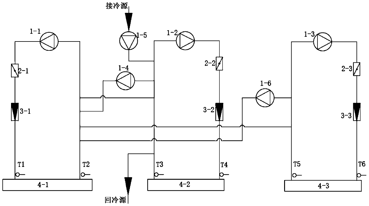
[0056] Such as image 3 As shown, an improved test device for testing chillers with heat recovery function, including the evaporator side circulation pipeline connected to the evaporator 4-1, and the condenser side circulation pipeline connected to the condenser 4-2 . The heat recovery unit side circulation pipeline connected to the heat recovery unit 4-3, the first water conversion circulation pipeline, the second water conversion circulation pipeline, and the third water conversion circulation pipeline. The evaporator 4-1 and the circulation pipeline on the evaporator side, the condenser 4-2 and the circulation pipeline on the condenser side, the circulation pipeline on the heat recovery unit and the heat recovery unit 4-3 all form a closed cycle. The circulation pipeline on the evaporator side is communicated with the circulation pipeline on the condenser side through the first water exchange pipeline, the circulation pipeline on the heat recovery side is connected with the...


PUM


Abstract

The invention belongs to the technical field of heat pump unit testing, and particularly relates to an improved water chilling unit testing device with a heat recovery function. The testing device comprises an evaporator side circulating pipeline connected with an evaporator, and a condenser side circulating pipeline connected with a condenser, the evaporator side circulating pipeline is communicated with the condenser side circulating pipeline through a first water mixing circulating pipeline; the device further comprises a heat recoverer side circulation pipeline connected with a heat recoverer. The heat recoverer side circulation pipeline and a heat recoverer form closed circulation. The device further includes a second water mixing circulating pipeline; the heat recoverer side circulation pipeline is communicated with an external cold source, the evaporator side circulation pipeline or the condenser side circulation pipeline through the second water mixing circulation pipeline. Thetesting device has the advantages that independent pipelines and equipment are arranged for the heat recoverer, the simulation experiment of the water chilling unit with the heat recovery function can be met, and the simulation experiment of partial heat recovery and total heat recovery can be carried out.

Description

[0001] The present invention is a divisional application, the filing date of the original application is September 27, 2018, the application number is 201811129878.X, and the name is a test device for testing chillers with heat recovery function. technical field [0002] The invention relates to the technical field of heat pump unit testing, in particular to an improved testing device for testing a chiller unit with heat recovery function. Background technique [0003] The heat released by the cooling water of the chiller is usually discharged to the surrounding environment by the cooling tower, which is a huge waste for places that need heat, such as hotels, factories, hospitals, etc., and at the same time brings a certain amount of waste heat pollution to the surrounding environment . The heat recovery technology is to recover and reuse a large amount of waste heat discharged to the outside during the operation of the chiller in a certain way. It can save energy, reduce e...

Claims


Application Information

Patent Timeline
Patent Type & Authority Applications(China)
IPC IPC(8): G01M99/00
CPCG01M99/002G01M99/005
Inventor 贾甲樊海彬钱雪峰马小津王显峰杨厚太李昀达
Owner HEFEI GENERAL MACHINERY RES INST
Why Eureka
Try Eureka