Test device for testing water chilling unit with heat recovery function
A chiller and testing device technology, applied in measuring devices, testing of machines/structural components, instruments, etc., to achieve large heat transfer temperature difference, reduce operating flow and overall energy consumption, and simplify cooling schemes
- Summary
- Abstract
- Description
- Claims
- Application Information
AI Technical Summary
Problems solved by technology
Method used
Image
Examples
Embodiment 1
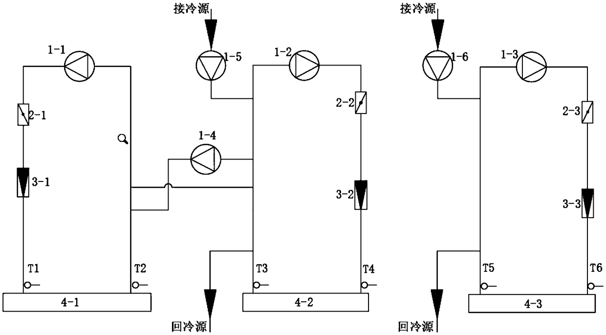
[0034] Such as figure 1 As shown, a test device for testing a chiller with heat recovery function includes an evaporator side circulation pipeline connected to the evaporator 4-1, a condenser side circulation pipeline connected to the condenser 4-2, and The heat recovery unit side circulation pipeline connected to the heat recovery unit 4-3, the first water conversion circulation pipeline, the second water conversion circulation pipeline, and the third water conversion circulation pipeline. The evaporator 4-1 and the circulation pipeline on the evaporator side, the condenser 4-2 and the circulation pipeline on the condenser side, the circulation pipeline on the heat recovery unit and the heat recovery unit 4-3 all form a closed cycle. The circulation pipeline on the evaporator side communicates with the circulation pipeline on the condenser side through the first water exchange circulation pipeline, the heat recovery side circulation pipeline communicates with the external coo...
Embodiment 2
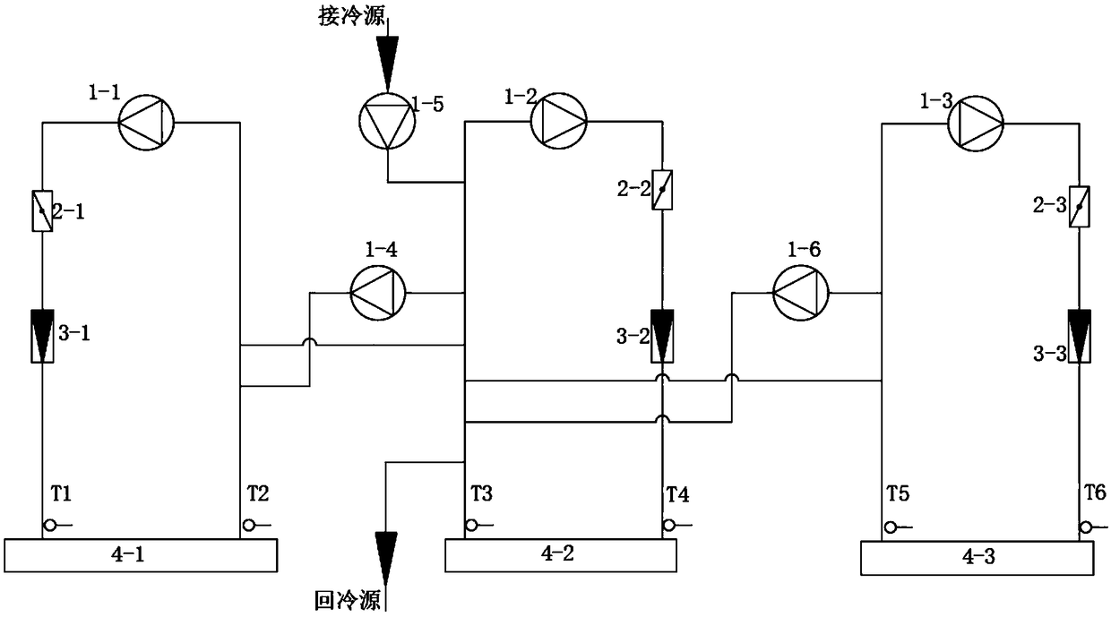
[0045] Such as figure 2 As shown, a test device for testing a chiller with heat recovery function includes an evaporator side circulation pipeline connected to the evaporator 4-1, a condenser side circulation pipeline connected to the condenser 4-2, and The heat recovery unit side circulation pipeline connected to the heat recovery unit 4-3, the first water conversion circulation pipeline, the second water conversion circulation pipeline, and the third water conversion circulation pipeline. The evaporator 4-1 and the circulation pipeline on the evaporator side, the condenser 4-2 and the circulation pipeline on the condenser side, the circulation pipeline on the heat recovery unit and the heat recovery unit 4-3 all form a closed cycle. The circulation pipeline on the evaporator side is communicated with the circulation pipeline on the condenser side through the first water exchange pipeline, and the circulation pipeline on the heat recovery side is communicated with the circul...
Embodiment 3
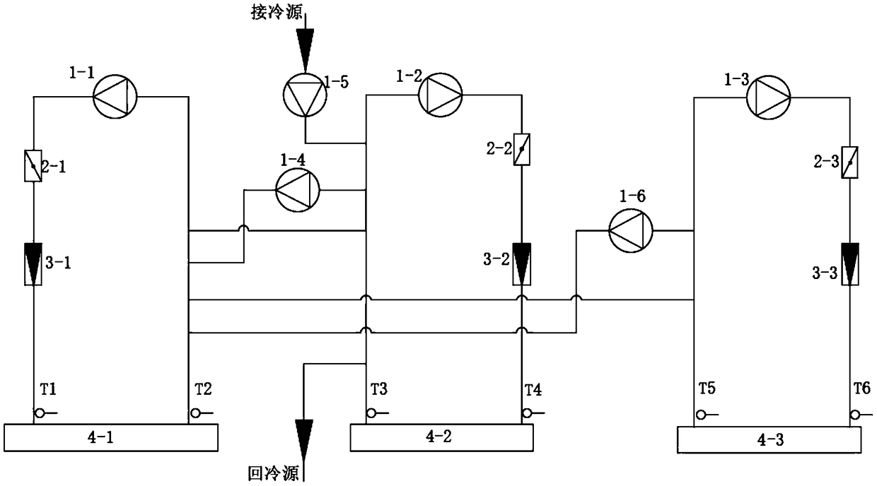
[0055] Such as image 3 As shown, a test device for testing a chiller with heat recovery function includes an evaporator side circulation pipeline connected to the evaporator 4-1, a condenser side circulation pipeline connected to the condenser 4-2, and The heat recovery unit side circulation pipeline connected to the heat recovery unit 4-3, the first water conversion circulation pipeline, the second water conversion circulation pipeline, and the third water conversion circulation pipeline. The evaporator 4-1 and the circulation pipeline on the evaporator side, the condenser 4-2 and the circulation pipeline on the condenser side, the circulation pipeline on the heat recovery unit and the heat recovery unit 4-3 all form a closed cycle. The circulation pipeline on the evaporator side is communicated with the circulation pipeline on the condenser side through the first water exchange pipeline, the circulation pipeline on the heat recovery side is connected with the circulation pi...
PUM
 Abstract
Description
Claims
Application Information
 - R&D
- Intellectual Property
- Life Sciences
- Materials
- Tech Scout
- Unparalleled Data Quality
- Higher Quality Content
- 60% Fewer Hallucinations
Browse by: Latest US Patents, China's latest patents, Technical Efficacy Thesaurus, Application Domain, Technology Topic, Popular Technical Reports.
© 2025 PatSnap. All rights reserved.Legal|Privacy policy|Modern Slavery Act Transparency Statement|Sitemap|About US| Contact US: help@patsnap.com


