System and method for adjusting position and angle of optical fiber based on machine vision

An angle adjustment and machine vision technology, which is applied in the direction of instruments, use feedback control, image data processing, etc., can solve problems such as low production efficiency, uncontrollable position, and poor adjustment accuracy, so as to improve production efficiency and adjustment accuracy , to achieve the effect of fully automatic adjustment

Active Publication Date: 2020-08-28
武汉来勒光电科技有限公司
View PDF6 Cites 6 Cited by
  • Summary
  • Abstract
  • Description
  • Claims
  • Application Information

AI Technical Summary

Problems solved by technology

[0003] However, this method mainly uses the naked eye to identify the position, the adjustment accuracy is poor, there is no feedback mechanism, the adjusted position is uncontrollable, and the production efficiency is not high

Method used


Image

  • System and method for adjusting position and angle of optical fiber based on machine vision
  • System and method for adjusting position and angle of optical fiber based on machine vision
  • System and method for adjusting position and angle of optical fiber based on machine vision

Examples


Embodiment 1

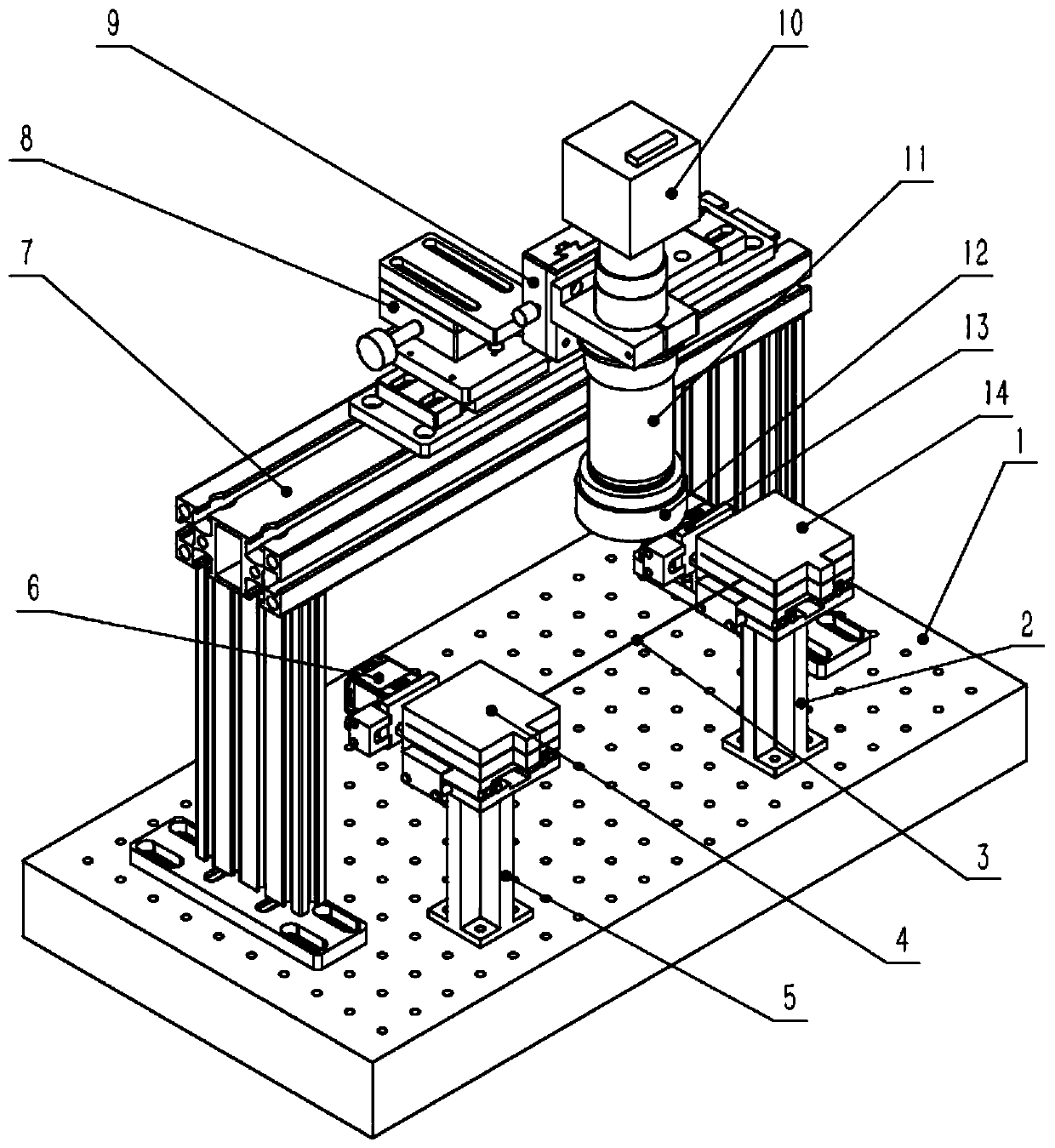
[0024] see figure 1 , this embodiment discloses a system for adjusting the position and angle of an optical fiber based on machine vision, including an industrial computer, an optical platform 1, and a CCD industrial camera 10 for taking images of optical fibers. The CCD industrial camera 10 is installed on the gantry 7 Above, the gantry 7 is installed on the optical platform 1, and the optical platform 1 is fixed with two supporting columns, which are respectively the left supporting column 5 and the right supporting column 2, and the left supporting column 5 is fixed with a left electric translation platform 6. The right electric translation platform 13 is fixed on the right support column 2, and the axis line of the electric shaft on the left electric translation platform 6 is parallel to the axis line of the electric shaft on the right electric translation platform 13 (on the left electric translation platform 6 The power output shaft axis line of the motor is parallel to ...

Embodiment 2

[0045] see Figure 1 to Figure 5 , this embodiment discloses a method for adjusting the position and angle of an optical fiber based on machine vision, including the following steps:

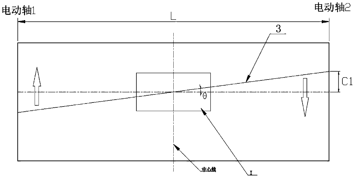
[0046] Obtain the fiber optic image currently captured by the CCD industrial camera, see figure 2 , the horizontal distance between the electric shafts at both ends of the optical fiber is L, the offset angle of the optical fiber center is θ, and the displacement to be adjusted for angle calibration is C1,

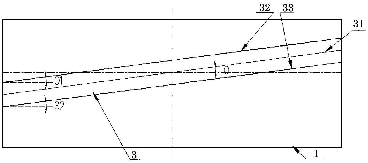
[0047] Adjust the angle so that the fiber angle is within the set target angle accuracy range, specifically including: obtaining the fiber image currently captured by the CCD industrial camera, performing edge detection calculations on the fiber image to obtain the upper and lower edges of the fiber in the camera coordinate system and the X-axis The included angles θ1 and θ2 are further calculated to obtain the current included angle θ between the centerline of the fiber and the X-axis, ...


PUM


Abstract

The invention discloses a system and method for adjusting a position and an angle of an optical fiber based on machine vision. The system comprises an industrial personal computer, an optical platformand a CCD industrial camera; the CCD industrial camera is mounted on the portal frame; the portal frame is mounted on the optical platform; two support columns are fixed on the optical platform; electric translation tables are respectively fixed on the two supporting columns; the axial leads of the electric shafts of the two electric translation tables are parallel; optical fiber clamps for clamping optical fibers are respectively supported on the two electric translation tables; two ends of the optical fiber are respectively clamped on the two optical fiber clamps; the industrial personal computer shoots the current position of the optical fiber by using an industrial camera, calculates the deviation distance between the current position and the target position and controls the electrictranslation platform to move, adjusts the optical fiber to a target position, detects feedback deviation of the optical fiber in real time for repeated fine adjustment, and controls a deviation valuewithin a precision range, According to the method, the optical fiber can be automatically adjusted to the target position of the CCD shooting area, the requirement for adjusting precision is met, andfull-automatic adjustment is achieved.

Description

technical field [0001] The invention relates to the field of optical fiber adjustment, in particular to a system and method for adjusting the position and angle of an optical fiber based on machine vision. Background technique [0002] The existing optical fiber adjustment equipment uses a camera to capture and amplify the optical fiber image, and manually adjusts the optical fiber clamp so that the optical fiber is in a horizontal and central position in human vision. [0003] However, this method mainly uses the naked eye to identify the position, the adjustment accuracy is poor, there is no feedback mechanism, the adjusted position is uncontrollable, and the production efficiency is not high. Contents of the invention [0004] The purpose of the present invention is to overcome the defects of the prior art, and provide a system and method for adjusting the position and angle of the optical fiber based on machine vision, which can automatically adjust the center position...

Claims


Application Information

Patent Timeline
Patent Type & Authority Applications(China)
IPC IPC(8): G06T7/00G06T7/13G06T7/73G05D3/12
CPCG06T7/0004G06T7/13G06T7/73G05D3/12G06T2207/10004G06T2207/30108
Inventor 张朋勇黄川
Owner 武汉来勒光电科技有限公司
Why Eureka
Try Eureka