
Device for realizing automatic evaporation of ceramic target materials through electron beam physical vapor deposition

A physical vapor deposition, ceramic target technology, applied in vacuum evaporation plating, ion implantation plating, metal material coating process and other directions, can solve problems such as unfavorable popularization and application, large manual workload, complex hardware structure, etc. Improve process stability, good thickness repeatability, uniform and stable composition

Active Publication Date: 2020-09-01
BEIHANG UNIV +1
View PDF10 Cites 2 Cited by
  • Summary
  • Abstract
  • Description
  • Claims
  • Application Information

AI Technical Summary

Problems solved by technology

As the electron beam moves outward from the center of the circle, the radius of the scanned ring becomes larger, while the scanning time of the electron beam on each ring remains unchanged, which will result in poor controllability of the target consumption. Using manual control to continuously move the electron beam to scan the beam on the target surface, the manual workload is large, and it will also lead to poor stability of target melting and evaporation, affecting the precise control of coating quality and thickness
[0004] In the patent with the publication number [US6589351B1], the automatic and stable evaporation of ceramic targets in the process of electron beam physical vapor deposition can be realized by optimizing the electron beam scanning strategy combined with laser monitoring, but the hardware structure of the device is complex, and the electron beam Streams require high controllability and stability, which is not conducive to popularization and application

Method used


Image

  • Device for realizing automatic evaporation of ceramic target materials through electron beam physical vapor deposition
  • Device for realizing automatic evaporation of ceramic target materials through electron beam physical vapor deposition
  • Device for realizing automatic evaporation of ceramic target materials through electron beam physical vapor deposition

Examples


Embodiment Construction

[0036] The technical solutions in the embodiments of the present invention will be clearly and completely described below in conjunction with the accompanying drawings in the embodiments of the present invention. Obviously, the described embodiments are only for illustration and are not intended to limit the present invention.

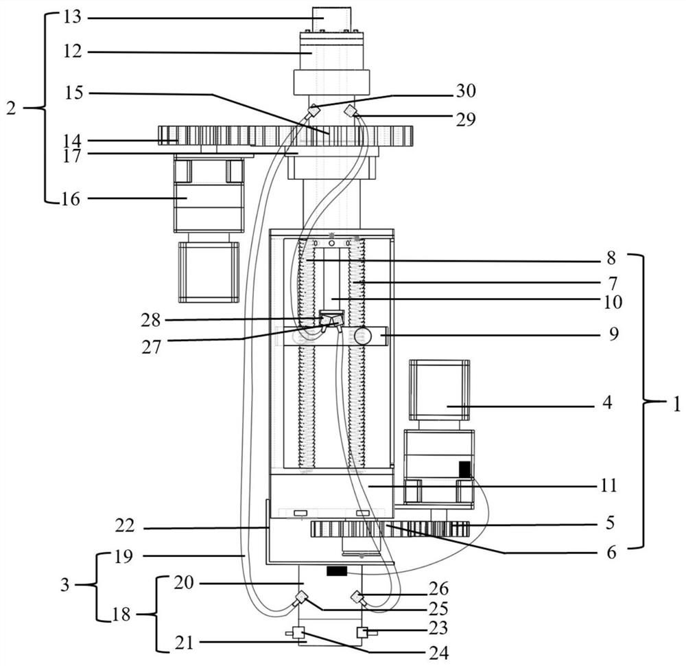
[0037] The present invention provides a device for automatically evaporating ceramic targets by electron beam physical vapor deposition, such as figure 1 As shown, including: lifting assembly 1, rotating assembly 2 and water cooling assembly 3; wherein,

[0038] The lifting assembly 1 is used to control the rising speed of the target, including the lifting motor 4, the lifting driving gear 5, the lifting driven gear 6, the first screw 7, the second screw 8, the lifting slider 9, the lifting rod 10 and the lifting frame 11; Wherein, the lifting motor 4 is connected with the lifting driving gear 5 for controlling the rotation of the lifting driving gear...


PUM


Abstract

The invention discloses a device for realizing automatic evaporation of ceramic target materials through electron beam physical vapor deposition. In the process of preparing a coating through the electron beam physical vapor deposition, a lifting assembly drives the target materials in a water-cooled crucible to automatically rise at a certain speed, a rotating assembly drives the target materialsin the water-cooled crucible to automatically rotate at a certain speed, and combined with the optimization of an electron beam current scanning method on the target materials, automatic, uniform andstable evaporation of the target materials during the process of the electron beam physical vapor deposition are realized, so that the process stability of the coating preparation process through theelectron beam physical vapor deposition is improved, and a high-quality coating with good thickness repeatability and uniform and stable composition is obtained.

Description

technical field [0001] The invention relates to the technical field of preparation of thermal barrier coatings, in particular to a device for realizing automatic evaporation of ceramic targets by electron beam physical vapor deposition. Background technique [0002] Electron beam physical vapor deposition (EB-PVD) technology is a technology that uses high-energy-density electron beams to heat the target material in a vacuum environment, evaporate it into a gas phase, and condense and deposit it on the substrate to form a coating. . In EB-PVD equipment, the beam spot size and beam spot position of the electron beam are controlled by the computer, which is beneficial to accurately control the thickness and uniformity of the coating. The crucible is usually water-cooled during the preparation process, and the target material is placed in the water-cooled crucible, which can avoid the chemical reaction between the evaporated material and the crucible at high temperature and aff...

Claims


Application Information

Patent Timeline
IPC IPC(8): C23C14/30
CPCC23C14/30
Inventor 彭徽滕晓丹王博郭洪波宫声凯
Owner BEIHANG UNIV
Learn More