
Waste gas purification equipment for garbage incinerator

A garbage incinerator and exhaust gas purification technology, which is applied in the direction of gas treatment, use of liquid separation agent, chemical instruments and methods, etc., can solve the problems of unfavorable environmental protection, air pollution, purification, etc., and achieve a strong practical effect

Active Publication Date: 2020-09-04
JIANGSU XINGXIN SEPARATION EQUIP MFR
View PDF8 Cites 3 Cited by
  • Summary
  • Abstract
  • Description
  • Claims
  • Application Information

AI Technical Summary

Problems solved by technology

[0003] A large amount of waste gas will be produced after waste incineration, so the waste gas is often purified with a purification furnace during waste incineration. At present, the waste gas generated in the waste incinerator mostly enters the secondary combustion chamber and is completely burned under the forced combustion of the burner. Then enter the spray dust collector to remove the dust in the exhaust gas, and then discharge it into the atmosphere through the chimney. However, when the exhaust gas is discharged after burning, the exhaust gas will be discharged out of the incinerator along with some harmful gases, which cannot be treated by the dust collector alone. These harmful gases are effectively purified, and then the exhaust gas is discharged into the air, which is easy to cause air pollution and is not conducive to environmental protection.

Method used


Image

  • Waste gas purification equipment for garbage incinerator
  • Waste gas purification equipment for garbage incinerator
  • Waste gas purification equipment for garbage incinerator

Examples


Embodiment 1

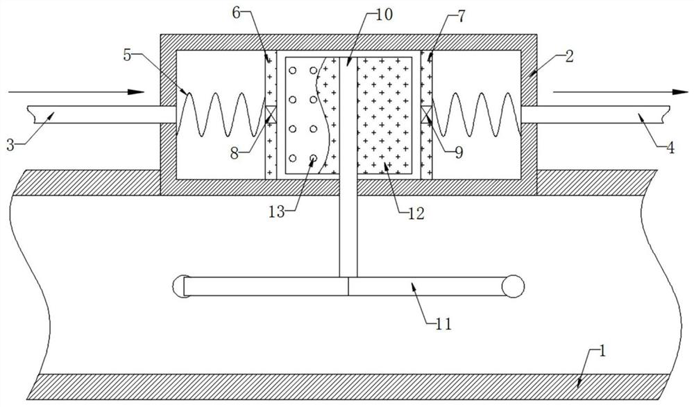
[0020] refer to figure 1 , a waste gas purification device for a waste incinerator, including a purification box 2 fixedly connected to the upper end of a water pipe 1, and further, the water pipe 1 is a cooling water circulation pipe in the incinerator, so that the device can be arranged together with the water pipe 1, which is simple and convenient. Strong practicability, the left side wall of the purification box 2 is connected with the intake pipe 3, the right side wall of the purification box 2 is connected with the exhaust pipe 4, and the inner wall of the purification box 2 is symmetrically fixed and connected with the first magnetic slide plate 6 and the second magnetic slide plate 6 through the telescopic spring 5. Two magnetic slides 7, in the purification box 2, between the first magnetic slide 6 and the second magnetic slide 7 are filled with a purifying agent, further, the purifying agent can be activated carbon adsorbent, and the inner wall of the purification box...

Embodiment 2

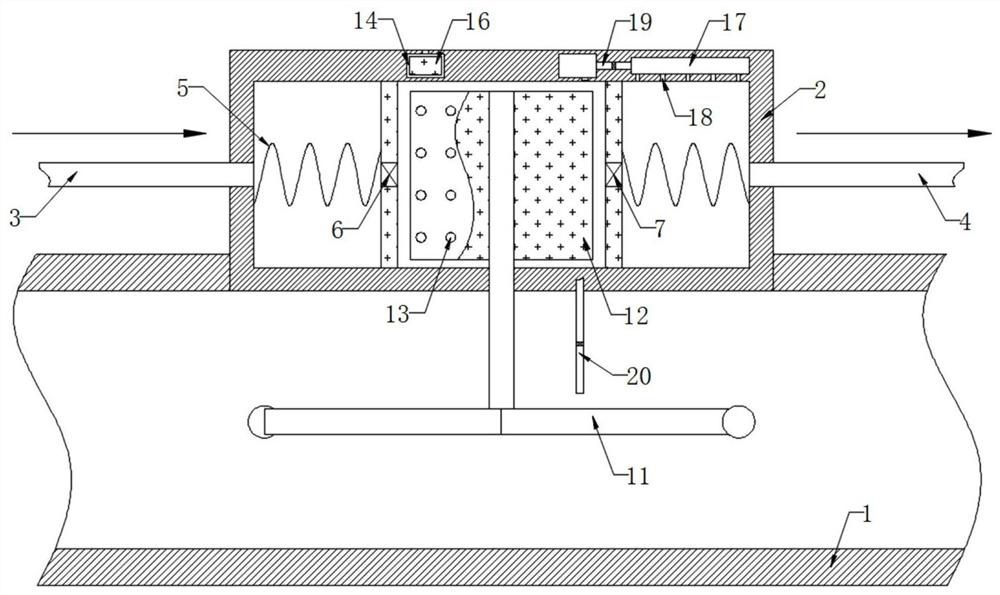
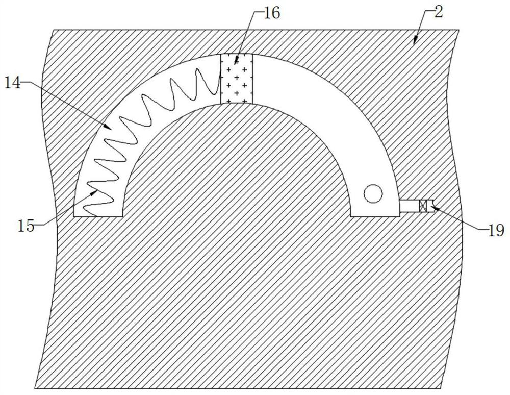
[0024] refer to Figure 2-3 , different from Embodiment 1, the upper end of the purification box 2 is provided with an arc-shaped cavity 14, and the inner wall of the arc-shaped cavity 14 is fixedly connected with a magnetic slide 16 through the return spring 15. Further, the arc-shaped cavity 14 is close to the inner wall of the return spring 15 A through hole is provided to balance the air pressure when the magnetic sliding plug 16 slides on the inner wall of the arc cavity 14. The inner top of the purification box 2 near the exhaust pipe 4 is provided with a cavity 17, and the inner bottom of the cavity 17 is provided with multiple outlets. The hole 18, the end of the arc-shaped cavity 14 away from the return spring 15 is connected to the inner wall of the cavity 17 through the one-way water inlet pipe 19, and the end of the arc-shaped cavity 14 far away from the return spring 15 is connected to the inner wall of the water pipe 1 through the one-way suction pipe 20, which ne...


PUM


Abstract

The invention discloses waste gas purification equipment for a garbage incinerator. The waste gas purification equipment comprises a purification box fixedly connected to the upper end of a water pipe; the left side wall of the purification box is connected with an air inlet pipe; the right side wall of the purification box is connected with an exhaust pipe; a first magnetic sliding plate and a second magnetic sliding plate are symmetrically and fixedly connected to the inner wall of the purification box through telescopic springs, a vertical rod is rotatably connected to the inner wall of thepurification box, the lower end of the vertical rod penetrates through the lower end of the purification box and is fixedly connected with a plurality of hydrodynamic wheels, and permanent magnet plates are symmetrically and fixedly connected to the side wall, located in the purification box, of the vertical rod. According to the invention, the two permanent magnet plates are driven by the hydrodynamic wheels to rotate ceaselessly; and then the first magnetic sliding plate and the second magnetic sliding plate are continuously close to and away from each other under the action of the elasticforce of a telescopic spring and the repulsive force of the permanent magnet plates, so that the purifying box continuously sucks waste gas to be in full contact with a purifying agent, a harmful gasin the waste gas is absorbed, and serious atmospheric pollution caused by exhaust of the waste gas into air is avoided.

Description

technical field [0001] The invention relates to the technical field of garbage treatment, in particular to a waste gas purification device for a garbage incinerator. Background technique [0002] Waste incineration is the process of reducing the volume of waste through oxidation at high temperature through appropriate thermal decomposition, combustion, melting and other reactions, and turning it into residue or molten solid matter. [0003] A large amount of waste gas will be produced after waste incineration, so the waste gas is often purified with a purification furnace during waste incineration. At present, the waste gas generated in the waste incinerator mostly enters the secondary combustion chamber and is completely burned under the forced combustion of the burner. Then enter the spray dust collector to remove the dust in the exhaust gas, and then discharge it into the atmosphere through the chimney. However, when the exhaust gas is discharged after burning, the exhaus...

Claims


Application Information

Patent Timeline
Patent Type & Authority Applications(China)
IPC IPC(8): B01D53/18B01D47/06B01F7/16B01F15/00B01F15/02
CPCB01D53/18B01D47/06B01D2258/0291B01F27/808B01F35/32015B01F35/718B01F35/7543B01F2101/25
Inventor 段拉宝
Owner JIANGSU XINGXIN SEPARATION EQUIP MFR
Learn More