Laser cutting head adjusting and converting system for laser cutting machine

A technology of laser cutting head and laser cutting machine, applied in laser welding equipment, welding equipment, metal processing equipment, etc., can solve the problem that the cutting speed and output power of the laser cutting head cannot be changed in time, the damage to the workpiece and the laser cutting head, and the The cutting head hits the workpiece, etc., to achieve the effect of fast and accurate focusing, fast focusing speed and accurate focusing

Inactive Publication Date: 2020-09-04
河南美聚生物科技有限公司
View PDF0 Cites 3 Cited by
  • Summary
  • Abstract
  • Description
  • Claims
  • Application Information

AI Technical Summary

Problems solved by technology

However, in the actual processing process, the capacitive sensor to measure the distance between the workpiece and the laser cutting head is often only suitable for workpieces with continuous and gentle undulations on the surface. When the surface of the workpiece is raised, the laser cutting head will often hit the workpiece. The laser cutting head causes damage; and when the thickness of the workpiece to be cut is uneven, the cutting speed, focus position and laser output power of the laser cutting head cannot be changed in time to adapt to the change in the thickness of the workpiece, which will easily affect the cutting effect of the workpiece

Method used


Image

  • Laser cutting head adjusting and converting system for laser cutting machine
  • Laser cutting head adjusting and converting system for laser cutting machine
  • Laser cutting head adjusting and converting system for laser cutting machine

Examples


Embodiment Construction

[0025] The present invention will be further described below in conjunction with the accompanying drawings and embodiments.

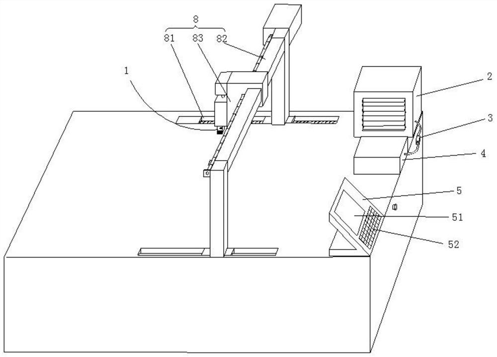
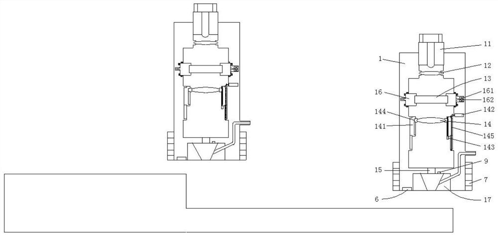
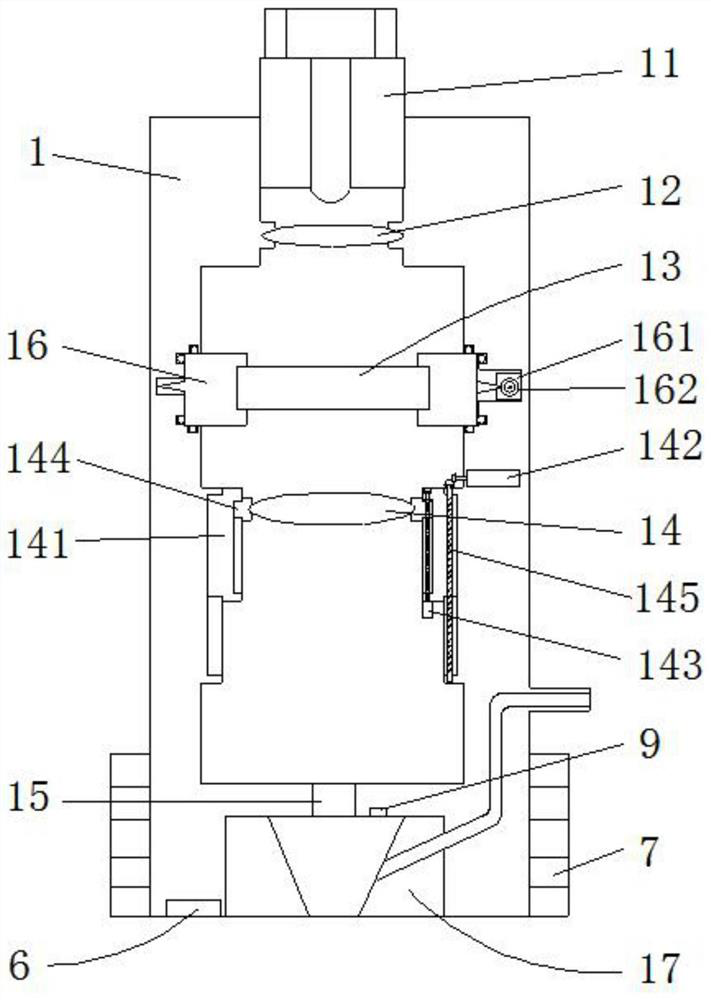
[0026] Please refer to figure 1 , figure 2 , image 3 , Figure 4 , Figure 5 as well as Figure 6 ,in figure 1 A structural schematic diagram of a preferred embodiment of the laser cutting head adjustment conversion system for laser cutting machines provided by the present invention; figure 2 Schematic diagram of obstacle avoidance for laser cutting head body processing workpiece; image 3 for figure 2 The structural schematic diagram of the laser cutting head body shown; Figure 4 for image 3 Schematic diagram of the structure of the focusing mirror shown; Figure 5 for image 3 The structural schematic diagram of the rotating circle and the cylindrical mirror shown; Figure 6 It is a schematic diagram of the laser power adjustment control of the laser cutting head adjustment conversion system for the laser cutting machine provided by ...


PUM


Abstract

The invention provides a laser cutting head adjusting and converting system for a laser cutting machine. The laser cutting head adjusting and converting system involves a laser cutting head body, rotating rings, a cylindrical mirror, a focusing mirror, an optical fiber laser, a digital potentiometer, a switching power supply, a controller, a capacitive sensor, obstacle avoidance sensors and a servo mechanism, wherein the laser cutting head body is arranged in the servo mechanism, the laser cutting head body is connected with the optical fiber laser, the rotating rings are rotationally arrangedin the laser cutting head body, the cylindrical mirror is arranged in the rotating rings, the focusing mirror is slidably arranged in the laser cutting head body, the capacitive sensor is arranged atthe end part of the laser cutting head body, the obstacle avoidance sensors are arranged on the side wall of the laser cutting head body, the optical fiber laser is electrically connected with the switching power supply through the digital potentiometer, and the controller is electrically connected with the digital potentiometer, the capacitive sensor and the obstacle avoidance sensors. The system ensures that the laser diameter, power and cutting speed are matched with the workpiece thickness.

Description

technical field [0001] The invention relates to the field of laser cutting machines, in particular to a laser cutting head adjustment conversion system for a laser cutting machine. Background technique [0002] In the control of laser cutting machine tools, due to the fluctuation of the workpiece surface or the deformation of the workpiece, the distance between the laser cutting head and the workpiece surface often changes, which affects the cutting effect. [0003] In the prior art, the laser cutting head is often equipped with a capacitive sensor, and the capacitance change is caused by the change of the distance between the capacitive sensor and the workpiece, and the distance between the laser cutting head and the workpiece is calculated by the capacitance change, according to the distance between the cutting head and the workpiece The distance between the laser cutting head and the surface of the workpiece is controlled by an independent height adjuster to control the z...

Claims


Application Information

Patent Timeline
IPC IPC(8): B23K26/38B23K26/08B23K26/70
CPCB23K26/0869B23K26/38B23K26/702
Inventor 谢双王杰
Owner 河南美聚生物科技有限公司
Why Eureka
Try Eureka