Collision energy-absorbing box with rotary folding concave corner

A collision energy-absorbing, rotary technology, applied to bumpers, vehicle parts, vehicle safety arrangements, etc., can solve the problems of weak defect resistance, structural stability, and fast impact speed, and achieve low production costs and convenient processing Effect

Active Publication Date: 2021-03-16
CHANGSHA UNIVERSITY OF SCIENCE AND TECHNOLOGY
View PDF10 Cites 0 Cited by
  • Summary
  • Abstract
  • Description
  • Claims
  • Application Information

AI Technical Summary

Problems solved by technology

However, considering the complex working conditions such as fast impact speed and uncertain impact load (maybe a frontal collision or an offset collision) during a car collision, the crash box also needs to have a good ability to resist defects.
[0004] In the actual collision process, the energy-absorbing effect of the existing crash-absorbing box is limited, and there are the following problems:
However, under the influence of geometric defects in this crease pattern, the sharp corners of the diamond concave corners are more sensitive to defects, and there are structural stability problems
[0006] 2. In order to overcome the shortcoming of the unstable deformation mode of the crash box, a small number of existing technologies achieve this goal by adding constraints, such as the publication number CN102700618A, titled "A thin-walled energy Absorber tube" patent, in which the diaphragms that act as reinforcements are arranged at certain intervals inside the thin-walled tube
Since the thin-walled energy absorbing tube adds an additional built-in structure and is precisely connected with the thin-walled tube, it brings difficulty to the processing technology
[0007] 3. In the actual collision process, there will be more complex load conditions, and the existing crash energy-absorbing box structure has the disadvantage of weak defect resistance, and cannot cope with complex collision loads

Method used


Image

  • Collision energy-absorbing box with rotary folding concave corner
  • Collision energy-absorbing box with rotary folding concave corner
  • Collision energy-absorbing box with rotary folding concave corner

Examples


Embodiment 1

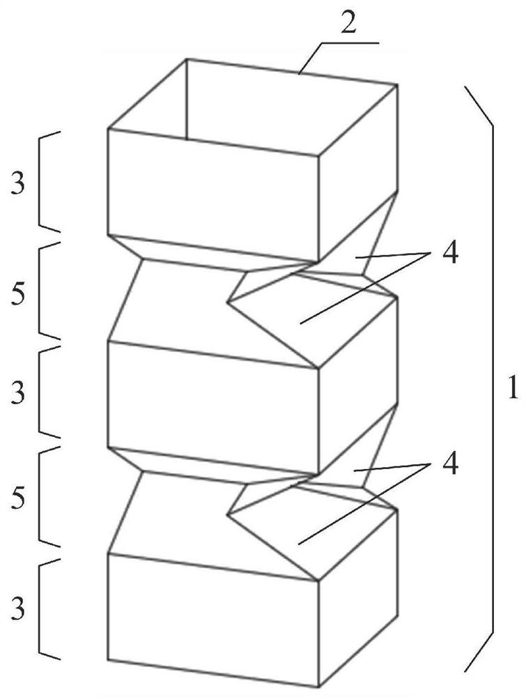
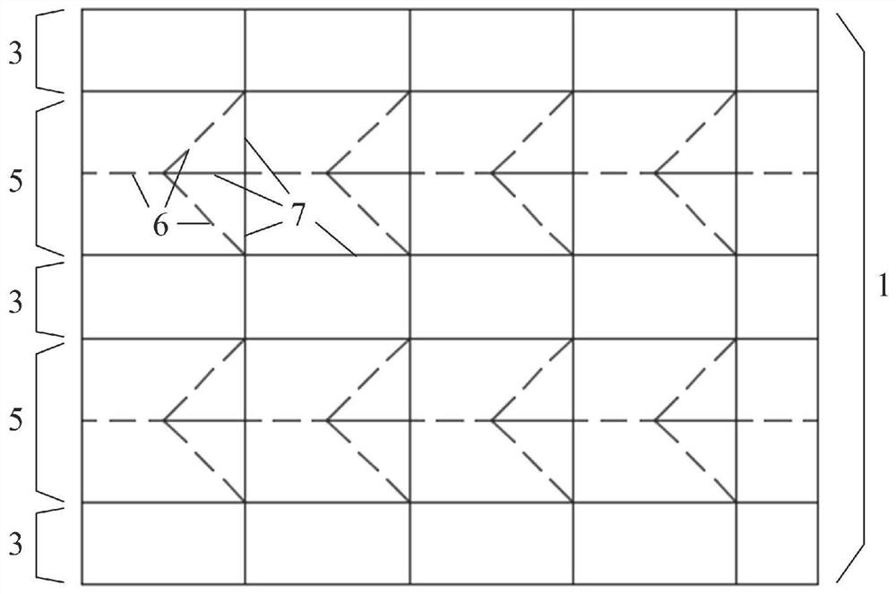
[0033] Example 1: figure 1 and figure 2 It is an embodiment of a crash box with a square section.

[0034] Such as figure 1 As shown, the square-section impact energy-absorbing box 1 is composed of multiple three-dimensional energy-absorbing areas 3 and type I folding energy-absorbing areas 5, and the three-dimensional energy-absorbing areas 3 and type I folding energy-absorbing areas 5 are arranged at intervals from top to bottom. Arranged in different ways; crash boxes of different heights can be obtained by superimposing several three-dimensional energy-absorbing areas and folding energy-absorbing areas along the axial direction. The Type I folding energy-absorbing area 5 forms circularly arranged rotary folding concave corners through crease lines and combined with rotating folding methods. The rotary folding concave corners in the Type I folding energy-absorbing area 5 are Type I folding concave corners 4. Type I folded concave angle 4 refers to the folded concave ang...

Embodiment 2

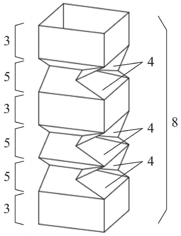
[0035] Example 2: image 3 and Figure 4 It is an embodiment of the hybrid type I crash crash box.

[0036] Such as image 3 As shown, the hybrid type I crash energy-absorbing box 8 is composed of a three-dimensional energy-absorbing area 3 and a type-I folding energy-absorbing area 5, and the three-dimensional energy-absorbing area 3 and the type I folding energy-absorbing area 5 are arranged in a top-to-bottom cross arrangement. Among them, one type I folded energy absorbing area 5 is arranged between two three-dimensional energy absorbing areas 3 , and two type I folded energy absorbing areas 5 are arranged continuously between the other two three-dimensional energy absorbing areas 3 . Each Type I folding energy-absorbing area 5 has a circle of rotary folding concave angles arranged in a circle, and each Type I folding energy-absorbing area 5 contains four Type I folding concave angles 4; Figure 4 As shown, there are three type I folding energy absorbing regions 5 in th...

Embodiment 3

[0037] Example 3: Figure 5 and Figure 6 It is an embodiment of the hybrid type II crash crash box.

[0038] Such as Figure 5As shown, the hybrid type II crash energy-absorbing box 9 is composed of a three-dimensional energy-absorbing area 3 , a type-I folding energy-absorbing area 5 and a type-II folding energy-absorbing area 11 . Among them, the type I folding energy-absorbing area 5 and the type II folding energy-absorbing area 11 are arranged at intervals on the hybrid type II crash energy-absorbing box 9 . The difference between the Type I folding energy-absorbing area 5 and the Type II folding energy-absorbing area 11 is that the rotary folding concave corner in the Type I folding energy-absorbing area 5 is the Type I folding concave angle 4, and the rotary folding concave angle in the Type II folding energy-absorbing area 11 is The folding reentrants are type II folding reentrants 10 , the rotation direction of type I folding reentrants 4 is clockwise, and the rota...


PUM


Abstract

The invention discloses a collision energy absorption box with rotary folding concave corners. The collision energy absorption box comprises three-dimensional energy absorption areas and folding energy absorption areas. The collision energy absorption box is composed of a plurality of three-dimensional energy absorption areas and folding energy absorption areas which are arranged in a crossed modefrom top to bottom, wherein the three-dimensional energy absorption area is a thin-wall pipe fitting with a polygonal section; and rotary folding concave corners arranged circumferentially are formedin the folding energy absorption area through crease lines in combination with a rotary folding mode. The surface of the whole collision energy absorption box structure is a deployable surface, machining is convenient, and the manufacturing cost is low. By means of two-stage buffering of the collision energy absorption box, the initial peak force generated in the collision process can be effectively reduced, and it can be guaranteed that the collision energy absorption box has the high energy absorption rate. Meanwhile, the circumferentially arranged rotary folding concave corners are compressed and deformed under the action of a load and form a restraining effect similar to that of a transverse partition plate, so that the collision energy absorption box has a stable deformation mode andgood defect resistance.

Description

technical field [0001] The invention relates to the technical field of automobile collision safety, in particular to a collision energy-absorbing box with a rotary folding concave corner. Background technique [0002] The crashworthiness of automobiles is one of the important indicators of automobile safety performance. At present, people usually install crash absorbing boxes of different structures on the parts of the car that are prone to collision, so as to effectively absorb the huge impact energy generated during the collision. The common crash absorber is a thin-walled structural pipe made of metal, which absorbs and dissipates the impact energy through the deformation of the thin-walled structural pipe, thereby ensuring the safety of the main structure of the car and the occupants of the car. [0003] The crashworthiness of crash-absorbing boxes is usually judged by the following indicators: (1) It has a low peak load to ensure that the force transmitted at the begin...

Claims


Application Information

Patent Timeline
Patent Type & Authority Patents(China)
IPC IPC(8): B60R19/02B60R19/34B60R19/04
CPCB60R19/02B60R19/023B60R19/04B60R19/34
Inventor 刘鑫陈德刘祥
Owner CHANGSHA UNIVERSITY OF SCIENCE AND TECHNOLOGY
Why Eureka
Try Eureka