Eureka AIR delivers breakthrough ideas for toughest innovation challenges, trusted by R&D personnel around the world.

Hull bilge keel base plate mounting method

An installation method and a technology of bilge keels, which are applied in the field of installation of hull bilge keel backing plates, can solve the problems of easy formation of molten pools on the outer plates, reduced service life of the outer plates, and increased weld cracking tendency, etc. Improve construction efficiency, improve reliability, and ensure the effect of heat insulation

Inactive Publication Date: 2020-09-04
GUANGZHOU SHIPYARD INTERNATIONAL LTD
View PDF5 Cites 3 Cited by
  • Summary
  • Abstract
  • Description
  • Claims
  • Application Information

AI Technical Summary

Problems solved by technology

[0003] In the prior art, the following two forms are often used for welding between two adjacent bilge keel backing plates: the first is to weld the two backing plates to the outer plate first, and then use CO 2 Gas shielded welding directly welds the gap between the two backing plates. This method will easily form a molten pool on the outer plate during the welding process, which will cause certain damage to the outer plate. In the subsequent use process, the keel will be stressed. Finally, the outer plate is torn through the backing plate, and the outer plate is easily torn at the molten pool, resulting in a decrease in the service life of the outer plate. In addition, the temperature field during the welding process will affect the paint on the outer plate around the weld. Cause damage and increase the subsequent paint repair process; the second is to add a copper gasket between the backing plate and the outer plate to protect the outer plate, but some copper elements will melt into the weld during the welding process Among them, the copper element will affect the structure of the weld and increase the cracking tendency of the weld. At the same time, because the thermal conductivity of the copper gasket is relatively good, the cooling speed of the weld is fast, the welding residual stress increases, and cracks will form at the root under the action of stress. And gradually spread to the surface of the weld, affecting the quality of the weld

Method used


Image

  • Hull bilge keel base plate mounting method
  • Hull bilge keel base plate mounting method
  • Hull bilge keel base plate mounting method

Examples


Embodiment Construction

[0039] The present invention will be further described in detail below in conjunction with the accompanying drawings and embodiments. It should be understood that the specific embodiments described here are only used to explain the present invention, but not to limit the present invention. In addition, it should be noted that, for the convenience of description, only some structures related to the present invention are shown in the drawings but not all structures.

[0040] In the description of the present invention, unless otherwise clearly specified and limited, the terms "connected", "connected" and "fixed" should be understood in a broad sense, for example, it can be a fixed connection, a detachable connection, or an integrated ; It can be a mechanical connection or an electrical connection; it can be a direct connection or an indirect connection through an intermediary, and it can be the internal communication of two components or the interaction relationship between two ...


PUM


Abstract

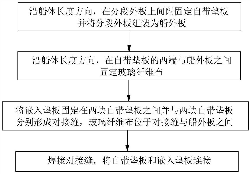
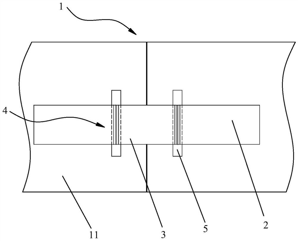
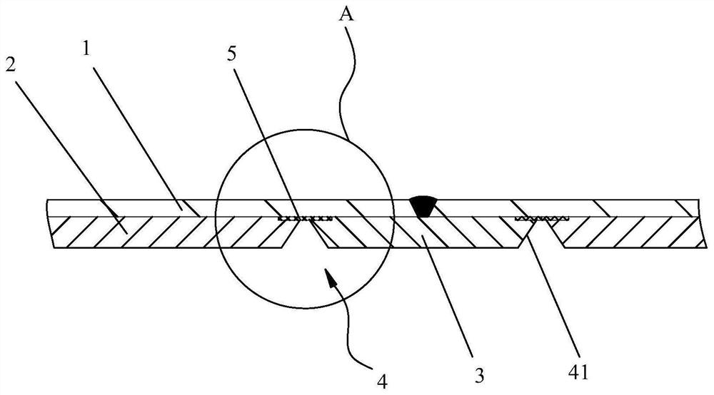
The invention relates to the technical field of shipbuilding, and discloses a hull bilge keel base plate mounting method. The ship bilge keel base plate mounting method comprises the steps of fixing built-in base plates to segmented outer plates at intervals in the length direction of a hull, and assembling the segmented outer plates into a ship outer plate; fixing glass fiber cloth between the two ends of the built-in base plate and the ship outer plate in the length direction of the hull; fixing an embedded base plate between the two built-in base plates, and forming a butt joint seam by theembedded base plate and the two built-in base plates, wherein the glass fiber cloth is located between the butt joint seam and the ship outer plate; and welding the butt joint seam so as to enable the built-in base plate and the embedded base plate to be connected. According to the hull bilge keel base plate mounting method, the base plate connection reliability is high, and the ship outer plateis not prone to damage.

Description

technical field [0001] The invention relates to the technical field of shipbuilding, in particular to a method for installing a hull bilge keel backing plate. Background technique [0002] The bilge keel of the ship is a structure installed on the outer plate of the bilge in the middle area of ​​the ship. It is mainly used to increase the damping when the ship rolls, thereby increasing the seakeeping and stability of the ship and greatly reducing the roll of the ship. The bilge keel usually consists of a backing directly connected to the shell plating and a keel connected to the backing. The outer plate of a large ship needs to be assembled and welded by multiple plates. Therefore, along the length of the ship, the backing plate of the bilge keel is often welded to the outer plate with multiple backing plates respectively, and the gap between two adjacent backing plates is Solder connection. [0003] In the prior art, the following two forms are often used for welding betw...

Claims


Application Information

Patent Timeline
IPC IPC(8): B63B73/20B63B39/06
CPCB63B39/06B63B2039/067B63B73/20
Inventor 林登强马金军刘亚伟
Owner GUANGZHOU SHIPYARD INTERNATIONAL LTD
Why Eureka
Eureka Blog
Learn More