Unloading type thin-walled box dead walls borne by oblique vertical sectional steel tube piles and construction technology

A technology of combining steel pipes and steel pipe piles, which is applied in sheet pile walls, artificial islands, water conservancy projects, etc., can solve the problem of poor compaction of the backfill of the retaining wall, failure of the support structure to achieve the expected effect, and impact on the filling Friction with ribs and other problems, to achieve good flood control and earthquake resistance, reduce the thickness of the retaining wall and the consumption of building materials, and achieve good pile-forming effects

Active Publication Date: 2020-09-04
ZHONGYUN INTERNATIONAL ENGINEERING CO LTD
View PDF4 Cites 3 Cited by
  • Summary
  • Abstract
  • Description
  • Claims
  • Application Information

AI Technical Summary

Problems solved by technology

However, in some specific cases, such as the design of the retaining wall with a wide bottom, it is inevitable to cross or longitudinally pass through the pressure pipes and underground corridors within the influence range below, and the specified compaction work cannot be performed. Mechanical layering and compaction will affect the friction between the filler and the ribs, which will cause the support structure to fail to achieve the expected effect or fail, and even cause damage to the protected pipelines and corridors below
In view of the above reasons, it is necessary to develop an unloading box-type retaining wall supported by oblique and vertical steel pipe piles and a construction method to solve the problem of large earth pressure and poor anchoring effect caused by poor compaction of the backfill of the retaining wall. Poor problems, and anti-slip, anti-overturning effect, and can effectively protect the important pipelines and corridors below

Method used


Image

  • Unloading type thin-walled box dead walls borne by oblique vertical sectional steel tube piles and construction technology
  • Unloading type thin-walled box dead walls borne by oblique vertical sectional steel tube piles and construction technology
  • Unloading type thin-walled box dead walls borne by oblique vertical sectional steel tube piles and construction technology

Examples


Embodiment

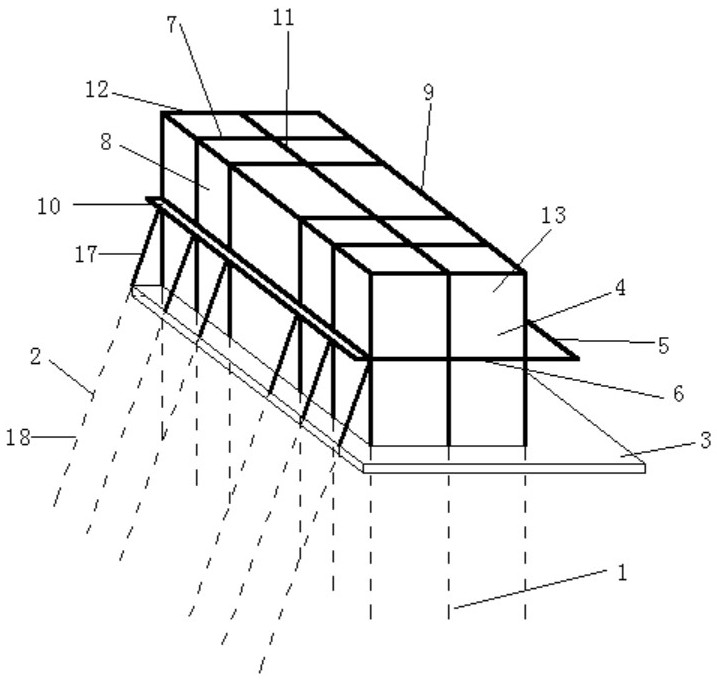
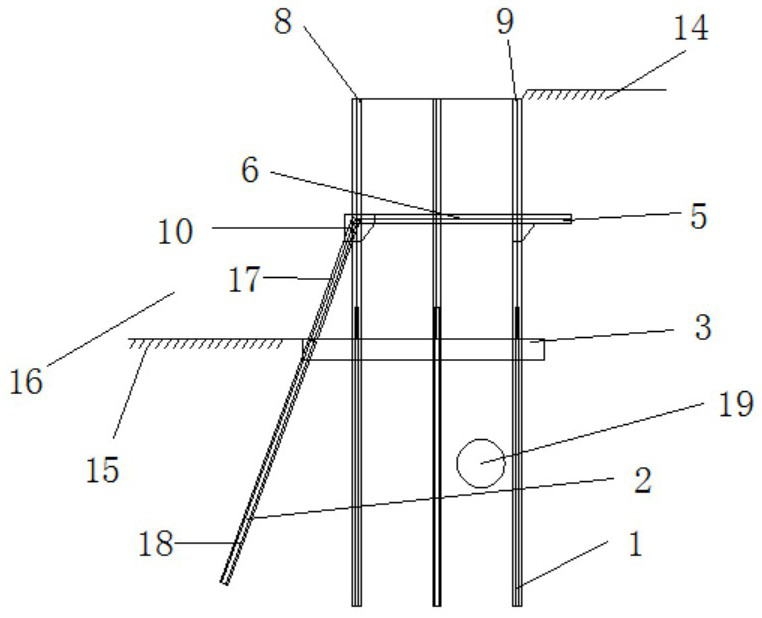
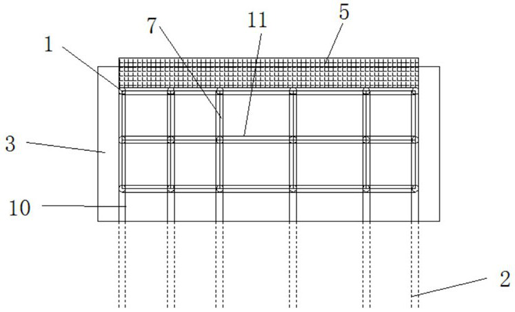
[0028] Example: such as figure 1 , figure 2 , image 3 As shown, including the foundation pit 16, the left side of the foundation pit 16 is provided with a low ground 15, the right side of the foundation pit 16 is provided with a high ground 14, the high ground 14 and the low ground 15 form a cliff-shaped structure, and the high ground 14 A box-shaped wall module 4 is provided relative to the lower ground 15. The box-shaped wall module 4 is a hollow structure. The box-shaped wall module 4 includes a rear outer wall 12, a front outer wall 13, and a left outer wall. The wall 8, the right exterior wall 9, the rear exterior wall 12, the front exterior wall 13, the left exterior wall 8, and the right exterior wall 9 are sequentially connected together to form a rectangular frame structure, and the internal relative positions of the box-shaped wall modules 4 A plurality of horizontal inner partition walls 7 are provided, a longitudinal inner partition wall 11 is provided at the r...


PUM


Abstract

The invention discloses unloading type thin-walled box dead walls borne by oblique vertical sectional steel tube piles. The unloading type thin-walled box dead walls comprise a foundation pit, whereinbox wall modules are arranged at relative positions of the high-place floor and the lower-place floor, and each box wall module comprises a rear outer wall, a front outer wall, a left outer wall anda right outer wall; a plurality of lateral inner separation walls are arranged at opposite positions in the box wall modules; longitudinal inner separation walls are arranged at opposite positions inthe box wall modules; middle stress plates are arranged at opposite positions in the box wall modules; leftwards-projected haunched beams are arranged on the left side of the middle stress plates; rightwards-projected unloading plates are arranged on the right side of the middle stress plates; rafts in horizontal arrangement are arranged at the bottoms of the box wall modules, and a plurality of vertical steel pipe piles in vertical arrangement are arranged at the bottoms of the rafts; and a plurality of oblique steel pipe piles are arranged at opposite positions of the left sides of the rafts. The unloading type thin-walled box dead walls have the beneficial effects that the unloading type thin-walled box dead walls can be suitable for foundation pit edges formed in different complex terrains, and are good in stability and convenient to construct.

Description

technical field [0001] The invention belongs to the technical field of slope and foundation pit engineering specialized in geotechnical engineering, and in particular relates to an unloading thin-walled box-shaped retaining wall supported by oblique and vertical combined steel pipe piles and a construction process. Background technique [0002] In the backfill area of ​​deep soil layer after construction, a high slope of more than ten meters is built. The traditional "panacea" support form of pile-anchor structure cannot be implemented due to constraints. Many projects adopt the form of reinforced soil retaining wall structure. However, in some specific cases, such as the design of the retaining wall with a wide bottom, it is inevitable to cross or longitudinally pass through the pressure pipes and underground corridors within the influence range below, and the specified compaction work cannot be performed. Mechanical layering and compaction will affect the friction between ...

Claims


Application Information

Patent Timeline
Patent Type & Authority Applications(China)
IPC IPC(8): E02D17/04E02D29/02E02D5/38E02D15/04
CPCE02D5/38E02D15/04E02D17/04E02D29/02E02D29/0233E02D29/0275
Inventor 刘阳陈景河刘桂芳霍亮贾俊超任亚军陈华丁瑞魏玉玺文金有
Owner ZHONGYUN INTERNATIONAL ENGINEERING CO LTD
Why Eureka
Try Eureka