Shear wall structure

A shear wall and power arm technology, applied in the direction of walls, building components, building structures, etc., can solve the problem of not being able to fully utilize the energy dissipation capacity of the damper, achieve strong applicability, and improve the bearing capacity and energy dissipation capacity Effect

Pending Publication Date: 2020-09-04
CHANGSHA UNIVERSITY OF SCIENCE AND TECHNOLOGY
View PDF0 Cites 3 Cited by
  • Summary
  • Abstract
  • Description
  • Claims
  • Application Information

AI Technical Summary

Problems solved by technology

Through the principle of leverage, the deformation of the inner energy-dissipating parts is amplified to overcome the shortcoming that the i

Method used


Image

  • Shear wall structure
  • Shear wall structure
  • Shear wall structure

Examples


Embodiment Construction

[0038] Below in conjunction with accompanying drawing, the present invention is described in detail:

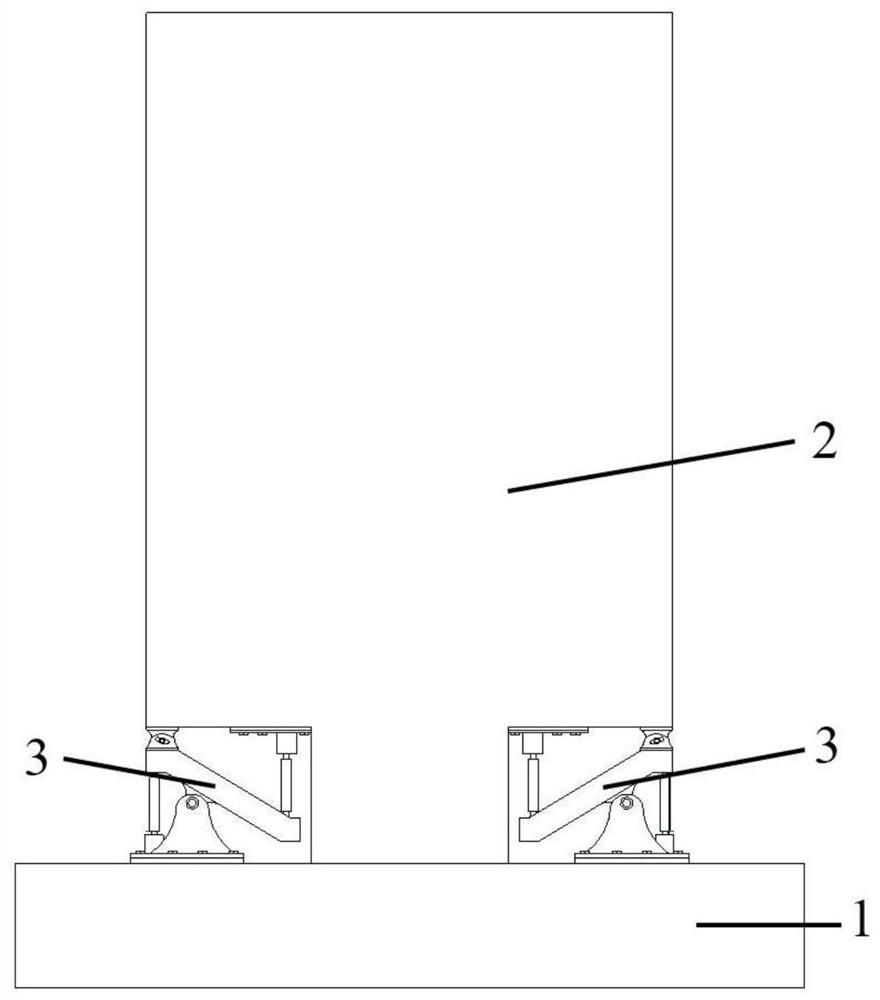
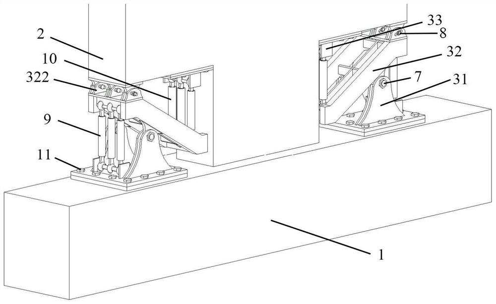
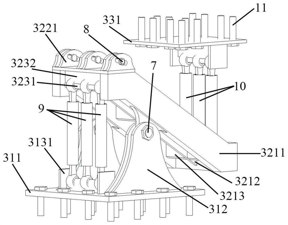
[0039] The shear wall structure of the present invention includes a foundation 1 and a shear wall 2 arranged on the foundation, wherein the shear wall 2 is symmetrically provided with reserved spaces on both sides of the bottom where it is connected to the foundation 1, and in each reserved space A deformation and amplification type energy dissipator 3 is installed. Install the deformed and amplified energy dissipator 3 in the reserved space at the foot of the shear wall 2, connect it with the second embedded part 5 through the pin shaft 7, and connect with the internal thread sleeves of the first embedded part 4 through the high-strength bolts 11 respectively. The connection between the barrel 42 and the internally threaded sleeve 62 of the third embedded part 6 is not only convenient for assembly, but also beneficial for quick replacement of the entire energy dissipator aft...


PUM


Abstract

The invention discloses a shear wall structure. The shear wall structure comprises a foundation and a shear wall arranged on the foundation. Two sides of the bottom, connected with the foundation, ofthe shear wall are symmetrically provided with reserved spaces, and a deformation magnification type energy dissipator is arranged in each reserved space. Each deformation magnification type energy dissipator comprises a first connection part, a second connection part and a third connection part, wherein the second connection part is provided with a middle hinge point which divides the second connection part into a power arm and a resistance arm in the length direction, the second connection part is connected with the upper end of the first connection part through the middle hinge point, the end of the power arm of the second connection part is provided with an outer buckling constraint type energy dissipation component connected with the first connection part, and the end of the resistance arm of the second connection part is provided with an inner buckling constraint type energy dissipation component connected with the third connection part. According to the shear wall structure, thedeformation of the inner energy dissipation components is magnified based on the lever principle, various types of dampers can be freely combined, the defect that the inner deformation of the shear wall is small under a horizontal load and the energy dissipation capacity of the dampers cannot be fully exerted is overcome, and the energy dissipation capacity of a failure part of the shear wall isimproved.

Description

technical field [0001] The invention belongs to the field of building structures, and in particular relates to a shear wall structure. Background technique [0002] As an important seismic structure system, the cast-in-place reinforced concrete shear wall structure has been widely used at home and abroad. According to previous earthquake damage investigations at home and abroad, compared with the frame structure, the shear wall structure system has a larger lateral stiffness. It has a high seismic bearing capacity, but under strong earthquakes, the concrete at the foot of the shear wall designed according to the bending failure mode is often easily crushed, and the compressed steel bars yield, making it difficult to repair and strengthen the structure. The seismic damage of cast-in-place reinforced concrete shear wall structures in the Wenchuan M8.8 earthquake in 2008 and the Chilean M8.8 earthquake in 2010 also showed that most of the shear wall feet were damaged to a large...

Claims


Application Information

Patent Timeline
IPC IPC(8): E04B2/00E04B2/56E04H9/02E04B1/98
CPCE04B1/98E04B2/00E04B2/56E04H9/021
Inventor 蒋友宝周浩康维张梦华
Owner CHANGSHA UNIVERSITY OF SCIENCE AND TECHNOLOGY
Why Eureka
Try Eureka