Gap protection side wing between train screen doors

A technology for screen doors and flanks, applied in stations, windows/doors, railway car body parts, etc., can solve the problems of inability to withstand wind resistance and vacuum pressure, gap protection flank breakage, affecting driving safety, etc., to reduce the amount of manual labor, The effect of reducing wind resistance and vacuum pressure and increasing the protective area

Active Publication Date: 2020-09-04
李晓琳 +2
View PDF5 Cites 0 Cited by
  • Summary
  • Abstract
  • Description
  • Claims
  • Application Information

AI Technical Summary

Problems solved by technology

[0002] The existing protective wings are very practical for the trains that stop at the platform. In order to improve the travel safety of passengers in the high-speed development of China's high-speed rail today, high-speed rail passenger stations need a more practical and reliable safety screen door system, and now both The platform gap protection flanks of some screen door systems cannot withstand the wind resistance and vacuum pressure generated by trains with a speed of 200 kilometers per hour. If such a scheme is adopted, when the high-speed train passes without stopping, the gap protection flanks may be directly broken, and the broken fragments will directly Affect driving safety and cause serious injury to the train

Method used


Image

  • Gap protection side wing between train screen doors
  • Gap protection side wing between train screen doors
  • Gap protection side wing between train screen doors

Examples


Embodiment Construction

[0019] The following will clearly and completely describe the technical solutions in the embodiments of the present invention with reference to the accompanying drawings in the embodiments of the present invention. Obviously, the described embodiments are only some, not all, embodiments of the present invention. Based on the embodiments of the present invention, all other embodiments obtained by persons of ordinary skill in the art without making creative efforts belong to the protection scope of the present invention.

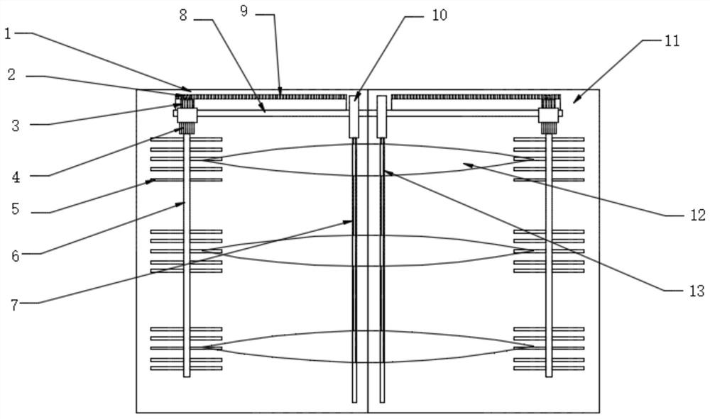
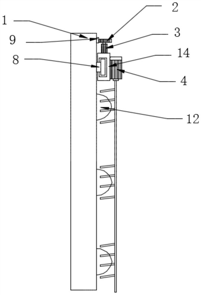
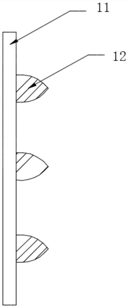
[0020] see Figure 1-5 , the present invention provides a technical solution: a gap protection flank between train screen doors, including a fixed door 1, a gear 2, a first motor 3, a second motor 4, a flexible brush 5, a rotating rod 6, and a plate groove 7 , slide rail 8, toothed belt 9, pneumatic cover 10, sliding door 11, protective wing 12, positioning groove 13, slider 14, cylinder 15, pneumatic rod 16, chute 17, slide plate 18, connecting block 19, movi...


PUM


Abstract

The invention discloses a gap protection side wing between train screen doors. The gap protection side wing comprises a fixed door, gears, first motors, flexible brushes, a sliding door, protection side wing bodies, positioning grooves, sliding blocks, air cylinders, pneumatic rods, sliding grooves, sliding plates, connecting blocks and moving baffles. According to the gap protection side wing, the plane stress manner of the windward surfaces of the protection side wing bodies is changed into the streamline dispersed stress manner, the split body combination type is changed into the type thatthe protection side wing bodies and the screen doors are integrally formed, thus the connecting precision between the protection side wing bodies and the sliding door is increased, and the air resistance and the vacuum pressure on the protection side wing bodies are greatly reduced; the slidable moving baffles are arranged on the sides of the fixed door and the sliding door, during use, the movingbaffles and the protection side wing bodies are arranged in a staggered manner, and the protection area is increased, so that the safety is improved; when the moving baffles are not used, the movingbaffles are overlapped with the protection side wing bodies, so that the resistance is reduced, and the safety is improved; and the flexible brushes are arranged on the protection side wing bodies, sothat the protection side wing bodies can be cleaned in a timed manner, and the cleanliness of the protection side wing bodies can be kept.

Description

technical field [0001] The invention relates to the technical field of protective equipment for train screen doors, in particular to a gap protection flank between train screen doors. Background technique [0002] The existing protective wings are very practical for the trains that stop at the platform. In order to improve the travel safety of passengers in the high-speed development of China's high-speed rail today, high-speed rail passenger stations need a more practical and reliable safety screen door system, and now both The platform gap protection flanks of some screen door systems cannot withstand the wind resistance and vacuum pressure generated by trains with a speed of 200 kilometers per hour. If such a scheme is adopted, when the high-speed train passes without stopping, the gap protection flanks may be directly broken, and the broken fragments will directly Affect driving safety and cause serious injury to the train. Contents of the invention [0003] The objec...

Claims


Application Information

Patent Timeline
IPC IPC(8): E06B7/28B61B1/02B08B1/04B08B13/00
CPCE06B7/28B61B1/02B08B13/00B08B1/32B08B1/12
Inventor 李晓琳潜文溪龚鹰翔
Owner 李晓琳
Why Eureka
Try Eureka