
Brushless magnetic drive submersible pump with built-in water cooling system

A technology of magnetic drive and water cooling system, which is applied to components, pumps, and pump devices of elastic fluid pumping devices, and can solve problems such as submersible pump burnout, short service life, and rotor damage, and extend service life , Guarantee normal operation and reduce temperature rise

Pending Publication Date: 2020-09-04
ZHONGSHAN JINGBAO ELECTRICAL
View PDF0 Cites 1 Cited by
  • Summary
  • Abstract
  • Description
  • Claims
  • Application Information

AI Technical Summary

Problems solved by technology

Existing problems: When the submersible pump is working, the winding coil of the stator will generate a lot of heat, which is the heat source of the submersible pump; but because the winding coil is arranged in the middle inner cavity of the sealed pump body, the heat on the winding coil cannot be dissipated. Heat island effect, the temperature rise of the winding coil is too high and the submersible pump will burn out; at the same time, in order to continue to work for a long time, the submersible pump reduces the heat generation on the winding coil by reducing the power, and the actual working power of the submersible pump cannot reach the rated power
In addition, the submersible pump needs to run continuously for a long time, which will cause the temperature rise of the ceramic shaft to be too high, which will accelerate its surface wear and damage the rotor in advance.
Therefore, the overall heat dissipation effect of this type of brushless submersible pump is poor, resulting in a short service life

Method used


Image

  • Brushless magnetic drive submersible pump with built-in water cooling system
  • Brushless magnetic drive submersible pump with built-in water cooling system
  • Brushless magnetic drive submersible pump with built-in water cooling system

Examples


Embodiment Construction

[0026] The present invention will be further described below in conjunction with the accompanying drawings.

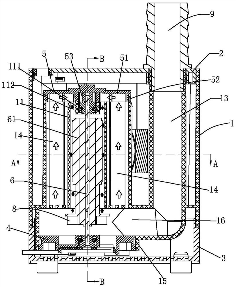
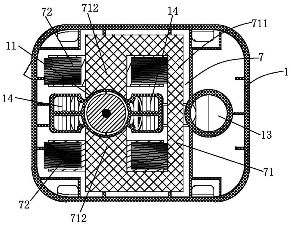
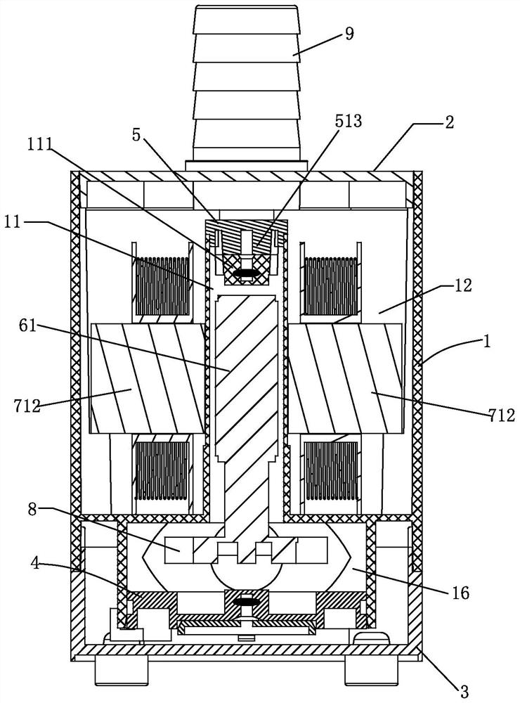
[0027] Such as figure 1 , figure 2 As shown, a brushless magnetic drive submersible pump with a built-in water cooling system is a brushless submersible pump with a built-in water cooling system, including a pump body 1, a pump cover 2, a water inlet casing 3, a lower end cover 4, an upper end cover 5, and a motor Shaft 6, rotor 61, stator 7, impeller 8 and water outlet pipe 9 arranged on the motor shaft, and the pump body 1 is provided with a rotor chamber 11, a stator chamber 12, a pump pressure chamber 16, a pump water inlet 15 and an outlet pipe 13 , the stator 7 includes an iron core 71 and a winding coil 72, and the motor shaft 6 rotates with the lower end cover 4 and the upper end cover 5;

[0028] The housing 1 also includes two longitudinal water passages 14 arranged in the stator cavity 12, such as figure 1 , as shown in Figure 5, the upper part of the lo...


PUM


Abstract

The invention relates to a brushless magnetic drive submersible pump with a built-in water cooling system. The brushless magnetic drive submersible pump comprises a pump body, a pump cover, a water inlet housing, an upper end cover, a lower end cover, a motor shaft, a rotor, a stator, an impeller and a water outlet pipe, and a rotor cavity, a stator cavity, a pump pressure cavity, a pump water inlet and a water outlet pipeline are arranged on the pump body; the shell further comprises two longitudinal water channels arranged in the stator cavity and a mounting hole in the upper end cover of the bottom plate, the upper parts of the longitudinal water channels are in communication with the upper part of the rotor cavity, and a water inlet hole is formed in the upper end cover; the lower endcover is buckled with the rotor cavity and the upper ends of the longitudinal water channels and is in liquid sealing with the rotor cavity and the upper ends of the longitudinal water channels, and awater flow heat exchange gap is formed between the rotor and the rotor cavity; and water enters from the bottom ends of the longitudinal water channels, flows through the longitudinal water channels,the water inlet holes in the upper end cover and the rotor cavity, and then is discharged from the bottom end of the rotor cavity to flow into the pump pressure cavity to form a water cooling system.Flowing water absorbs heat on a coil and the rotor, so that the temperature rise of rotating shafts of the coil and the rotor is effectively reduced, and the service life of the submersible pump is prolonged.

Description

technical field [0001] The invention relates to a brushless magnetic drive submersible pump, in particular to a brushless magnetic drive submersible pump with a built-in water cooling system. Background technique [0002] At present, the brushless magnetic drive submersible pump of the prior art includes a pump body, a pump cover, an inlet casing, an upper end cover, a lower end cover, a rotor, a stator, an impeller, an outlet pipe and a control circuit board; the pump body is provided with a rotor cavity, The stator cavity and the water outlet pipeline, the rotor includes a ceramic rotating shaft and a magnetic core, and the impeller is arranged at one end of the ceramic rotating shaft. The stator includes an iron core and winding coils, the upper end cover and the lower end cover are fastened with the two ends of the rotor chamber, the motor shaft is connected with the bearings on the upper end cover and the lower end cover, the stator and the circuit board are potted with...

Claims


Application Information

Patent Timeline
Patent Type & Authority Applications(China)
IPC IPC(8): F04D13/08F04D29/58H02K5/20H02K9/19H02K1/20H02K9/197
CPCF04D13/08F04D29/5806H02K1/20H02K5/20H02K9/19H02K9/197
Inventor 卢培胤
Owner ZHONGSHAN JINGBAO ELECTRICAL
Learn More