Supercharge Your Innovation With Domain-Expert AI Agents!

Multistage redundancy mutual inspection motor controller and control method

A technology of motor controller and control method, which is applied in the direction of motor control, motor speed or torque control, computer control, etc., and can solve the problem that the controller cannot control multiple motors together, without further comparison and setting, and motor control To avoid issues such as reduced reliability of the device, to prevent direct connection, ensure information retention, and increase reliability and stability

Active Publication Date: 2020-09-04
天紫虹阳(唐山)电机有限公司
View PDF4 Cites 0 Cited by
  • Summary
  • Abstract
  • Description
  • Claims
  • Application Information

AI Technical Summary

Problems solved by technology

The motor controller is the main source of power for various moving objects. Its performance, characteristics, and reliability determine the performance of the entire motion system. Traditional motor controllers generally use a processing chip to control a motor, or a The processing chip plus an auxiliary chip controls one or more motors, but when controlling the motor, at the same time, the traditional motor controller does not have chip-level correction and mutual inspection, and at the same time, the control method is single, the control mode is single, the reliability is poor, and it is only applicable to specific It is not suitable for all kinds of motors, and many controllers cannot control multiple motors at the same time, and the PWM output of the motor control signal is only solved by the algorithm of the processor, without further comparison and adjustment
These defects often cause the motor controller to be dedicated every time, which increases the cost of research and development. At the same time, the reliability of the motor controller is reduced, the applicability is reduced, and there is no redundancy. Once a problem occurs, the entire system will crash. Brings use constraints and research constraints to R&D and products

Method used


Image

  • Multistage redundancy mutual inspection motor controller and control method
  • Multistage redundancy mutual inspection motor controller and control method
  • Multistage redundancy mutual inspection motor controller and control method

Examples


Embodiment Construction

[0063] The present invention will be further described in detail below in conjunction with the accompanying drawings and embodiments.

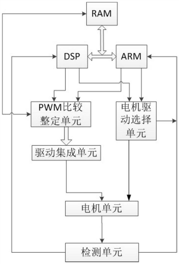
[0064] Such as figure 1 As shown in the schematic diagram of the motor controller, it includes a RAM, a DSP controller, an ARM controller, a PWM comparison and setting unit, a motor drive selection unit, a drive integration unit, a motor unit and a detection unit.

[0065] Such as figure 1 As shown in the schematic diagram of the motor controller, in the motor controller, the RAM is connected to the DSP controller and the ARM controller, and the RAM is connected to the PWM comparison and setting unit; the DSP controller and the ARM controller are connected to form a dual processor. When one control chip or motor breaks down, another control chip can be used as a backup to ensure the reliability of the controller. At the same time, the DSP controller and the ARM controller are connected to the PWM comparison and setting unit, connected to the...


PUM


Abstract

The invention relates to a multistage redundancy mutual detection motor controller and a control method. The controller comprises an RAM, a DSP controller, an ARM controller, a PWM comparison settingunit, a motor drive selection unit, a drive integration unit, a motor unit and a detection unit. The RAM is connected with the DSP controller, the ARM controller and the PWM comparison setting unit, and the DSP controller is connected with the ARM controller; the DSP controller and the ARM controller are connected with the PWM comparison setting unit, the motor drive selection unit and the detection unit. The PWM comparison setting unit is connected with the drive integration unit, the drive integration unit is connected with the motor unit, the motor drive selection unit is connected with themotor unit, and the motor unit is connected with the detection unit. According to the invention, a multi-stage redundant structure is realized, and the mutual detection of the dual processors, a mutually matched control mode and a multi-mode control method are realized at the same time.

Description

technical field [0001] The invention relates to the technical field of motor control, in particular to a multi-level redundant mutual detection motor controller and a control method. Background technique [0002] With the development of power electronics technology, motor controllers have become an important part of modern motion control. Motor controllers are widely used in the fields of injection molding machines, textile machinery, packaging machinery, CNC machine tools, and aerospace fields. The motor controller is the main source of power for various moving objects. Its performance, characteristics, and reliability determine the performance of the entire motion system. Traditional motor controllers generally use a processing chip to control a motor, or a The processing chip plus an auxiliary chip controls one or more motors, but when controlling the motor, at the same time, the traditional motor controller does not have chip-level correction and mutual inspection, and a...

Claims


Application Information

Patent Timeline
Patent Type & Authority Applications(China)
IPC IPC(8): H02P29/00H02P5/00G05B19/042
CPCH02P29/00H02P5/00G05B19/0421
Inventor 董立军
Owner 天紫虹阳(唐山)电机有限公司
Features
  • R&D
  • Intellectual Property
  • Life Sciences
  • Materials
  • Tech Scout
  • Unparalleled Data Quality
  • Higher Quality Content
  • 60% Fewer Hallucinations
Learn More