Current-adjustable and PWM flicker controlled constant-current driving circuit and control method

A constant current drive and control circuit technology, applied in the use of electrical components, semiconductor lamps, etc., can solve the problems of unable to meet the requirements of LED light source flicker control, pulse signal speed-up and pulse width control, etc., to achieve high stability and intelligence The effect of control requirements

Active Publication Date: 2020-09-04
CASI VISION TECH (LUOYANG) CO LTD
View PDF7 Cites 20 Cited by
  • Summary
  • Abstract
  • Description
  • Claims
  • Application Information

AI Technical Summary

Problems solved by technology

The constant current output or constant current pulse output circuit of the above literature has the following disadvantages: one is that the negative feedback loop does not control the pulse signal speed up and pulse width, and the quality of the output signal depends on the performance of the sampling resistor and the operational amplifier; the other is It cannot control the output of different current values ​​at different PWM pulse periods, and cannot meet the flicker control requirements of LED light sources in industrial machine vision.

Method used


Image

  • Current-adjustable and PWM flicker controlled constant-current driving circuit and control method
  • Current-adjustable and PWM flicker controlled constant-current driving circuit and control method
  • Current-adjustable and PWM flicker controlled constant-current driving circuit and control method

Examples


Embodiment Construction

[0039] Examples of the present disclosure will now be described more fully with reference to the accompanying drawings. The following description is merely exemplary in nature and is not intended to limit the disclosure, application or uses.

[0040] Example embodiments are provided so that this disclosure will be thorough, and will fully convey the scope to those who are skilled in the art. Numerous specific details are set forth such as examples of specific components, devices and methods, to provide a thorough understanding of embodiments of the present disclosure. To those skilled in the art, specific details need not be employed, example embodiments may be embodied in many different forms, and neither should be construed to limit the scope of the disclosure. In some example embodiments, well-known processes, well-known structures, and well-known technologies are not described in detail.

[0041] The technical problems raised by the present disclosure will be described i...


PUM


Abstract

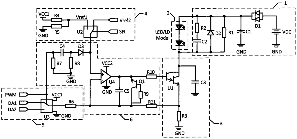
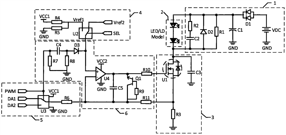
The invention relates to a current-adjustable and PWM flicker control constant-current driving circuit, which comprises a power supply and protection circuit (1), an LED or LD module (2), an MCU control circuit (7), a constant-current driving and current sampling circuit (3), a reference voltage setting circuit (4), a current setting and flicker control circuit (5) and a feedback and compensationcircuit (6). The constant-current driving and current sampling circuit is used for realizing adjustment of current output. The reference voltage setting circuit is used for setting reference voltageof the output current. The current setting and flicker control circuit is used for setting a pulse or a constant current value and setting frequency and pulse width. The feedback and compensation circuit realizes current feedback and dynamic compensation of the system, achieves the purpose of stabilizing current output, and has the effects of improving the rising speed of output current and widening the width of the output current. According to the invention, the constant current or pulse current of the LED or LD module can be adjusted, PWM adjustment and flicker control of the pulse current can be carried out, and the requirement of constant current driving in an LED light source and an LD laser system in a machine vision system can be met.

Description

technical field [0001] The invention relates to the technical field of novel circuits, in particular to a constant current drive circuit with adjustable current and PWM flash frequency control and a control method. Background technique [0002] At present, LEDs are becoming more and more common in lighting applications, especially in machine vision systems, where LEDs have become the most commonly used light source for capturing high-definition images. LD lasers have been widely used in optical fiber communication, laser fuze, laser radar, laser detection, laser guidance, industrial processing and other fields. In order to obtain high-efficiency, high-stability LED light source or LD laser output, their common feature is to use constant current or constant current pulse for driving. [0003] In the machine vision system, the LED light source is the preferred light source for shooting high-definition images. The LED light source should cooperate with the high-definition came...

Claims


Application Information

Patent Timeline
Patent Type & Authority Applications(China)
IPC IPC(8): H05B45/345H05B45/325H05B45/335
CPCH05B45/345H05B45/325H05B45/335Y02B20/30
Inventor 不公告发明人
Owner CASI VISION TECH (LUOYANG) CO LTD
Why Eureka
Try Eureka