Bundled steel wire core rod as well as metal pipe wall-reducing extension method and device

A metal pipe, steel wire core technology, applied in metal processing equipment, unloading mandrels, manufacturing tools, etc., can solve the problems of difficult processing and manufacturing, limited use range, long length, etc., to achieve simple and convenient production, increase strength and internal surface area , the effect of low stick force

Active Publication Date: 2020-09-08
TAIYUAN UNIVERSITY OF SCIENCE AND TECHNOLOGY
View PDF7 Cites 1 Cited by
  • Summary
  • Abstract
  • Description
  • Claims
  • Application Information

AI Technical Summary

Problems solved by technology

In addition, especially for mandrels with small diameters and long lengths, it is difficult to process and manufacture, which limits their application range

Method used


Image

  • Bundled steel wire core rod as well as metal pipe wall-reducing extension method and device
  • Bundled steel wire core rod as well as metal pipe wall-reducing extension method and device
  • Bundled steel wire core rod as well as metal pipe wall-reducing extension method and device

Examples


Embodiment 1

[0034] A magnesium alloy billet pipe with an outer diameter of 10 mm, a wall thickness of 1.5 mm, and a length of 240 mm is drawn through wall-reducing extension to obtain a magnesium alloy pipe with an outer diameter of 8 mm, a wall thickness of 0.5 mm, and a length of 900 mm.

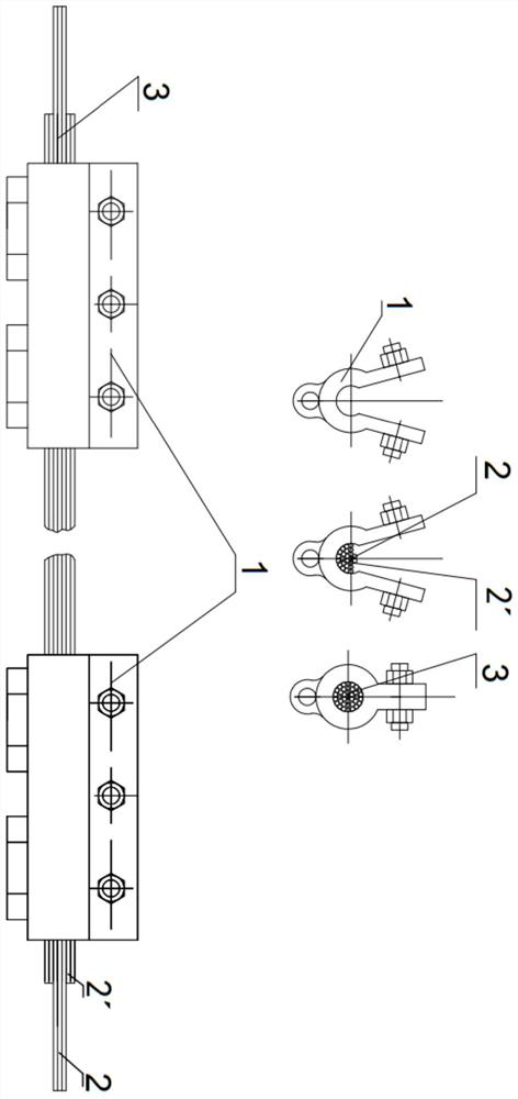
[0035] [1] 37 high-carbon steel wires with a diameter of 1 mm are used, 30 of which are 1000 mm in length, and 7 of which are 1100 mm in length. The steel wires are clamped together by 6 mandrel clamps, the 1100mm long steel wire is placed in the middle, and the 1000mm long steel wire is on the periphery to form a steel wire bundle, which becomes a bundled steel wire mandrel after clamping.

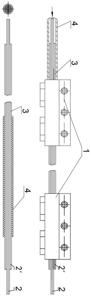
[0036] [2] Feed the bundled steel wire mandrels into the magnesium alloy billet tube material with an outer diameter of 10mm, a wall thickness of 1.5mm, and a length of 240mm. During the feeding process, the mandrel clamps are opened and removed one by one.

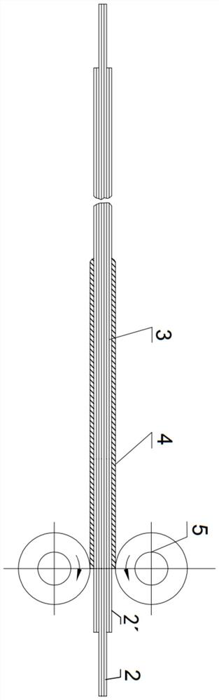
[0037] [3] Place the magnesium alloy billet tube that ...

Embodiment 2

[0042] A titanium alloy blank pipe with an outer diameter of 15mm, a wall thickness of 2mm, and a length of 240mm is drawn by wall reduction to obtain a titanium alloy pipe with an outer diameter of 12mm, a wall thickness of 1mm, and a length of 600mm.

[0043] [1] 32 high-carbon steel wires with a diameter of 1.5mm are used, 25 of which are 700mm in length, and 7 of which are 800mm in length. The steel wires are clamped together by 6 mandrel clamps, the 800mm long steel wire is placed in the middle, and the 700mm long steel wire is on the periphery to form a steel wire bundle, which becomes a bundled steel wire mandrel after clamping.

[0044] [2] Feed the bundled steel wire mandrel into the titanium alloy billet pipe with an outer diameter of 15mm, a wall thickness of 2mm, and a length of 240mm, and open and remove the mandrel clamps one by one during the feeding process.

[0045] [3] Put the titanium alloy billet pipe that penetrates the bundled steel wire mandrel on a thre...


PUM

PropertyMeasurementUnit
lengthaaaaaaaaaa
lengthaaaaaaaaaa
diameteraaaaaaaaaa

Abstract

The invention provides a bundled steel wire core rod as well as a metal pipe wall-reducing extension method and device, and belongs to the technical field of metal pipe machining. The bunched steel wire core rod is composed of a plurality of hard steel wires, the number, the length and the shape of the hard steel wires are determined according to the inner diameter size and the length of a machined pipe, and the steel wires are clamped together through a plurality of core rod clamps to form the bunched steel wire core rod. According to the method, the pipe penetrating into the core rod is placed on a reducing machine, and a gap between the pipe and the core rod is eliminated; then the pipe is conveyed to a drawing machine for wall reduction and extension; and after the drawing is finished,the rod is removed. The rod removing process comprises the following two steps of 1, blocking short steel wires by using a stop plate, clamping long steel wires in the core rod by using a jaw of a rod removing trolley, and pulling out the long steel wires to loosen the short steel wires in the core rod; and 2, blocking the pipe by the stop plate, and dragging the short steel wires out by the rodremoving trolley to complete rod removing. The inner surface of the pipe is subjected to finishing according to requirements after the rod removing is finished, so that the pipe with longitudinal ribswith different heights on the inner wall is obtained.

Description

technical field [0001] The invention belongs to the technical field of metal pipe processing, and in particular relates to a bundled steel wire mandrel and a metal pipe wall-reducing extension method and a device thereof. Background technique [0002] At present, in the production process of metal pipe wall reduction and deformation processing, the mandrels used are all solid mandrels made of single-layer metal, and there are two main forms: [0003] (1) Short mandrel processing: The main form of short mandrel processing method is the cold rolling and cold drawing process of metal pipes. It is characterized in that the length of the mandrel is slightly longer than the length of the deformation zone of the metal pipe, the mandrel has a fixed position in the deformation zone during the deformation process, and there is relative movement between the mandrel and the metal pipe. Due to the difficulty of lubrication between the surface of the mandrel and the contact surface of th...

Claims


Application Information

Patent Timeline
Patent Type & Authority Applications(China)
IPC IPC(8): B21C1/24B21C3/16B21C9/00B21C45/00
CPCB21C1/24B21C3/16B21C9/00B21C45/00
Inventor 帅美荣常彬彬楚志兵王建梅秦建平刘鑫李海斌
Owner TAIYUAN UNIVERSITY OF SCIENCE AND TECHNOLOGY
Why Eureka
Try Eureka