Test plot for separately monitoring field slope surface runoff and layered interflow

A technology for surface runoff and test plots, which is applied in soil material testing, flow/mass flow measurement, liquid/fluid solid measurement, etc. It can solve problems such as large errors in soil flow monitoring, inability to effectively segment soil flow, and inability to monitor, etc., to achieve The effect of reducing monitoring errors

Pending Publication Date: 2020-09-08
江西省水利科学院
View PDF1 Cites 0 Cited by
  • Summary
  • Abstract
  • Description
  • Claims
  • Application Information

AI Technical Summary

Problems solved by technology

[0003] At present, there is no complete monitoring device for surface runoff and soil flow in the market. The past surface runoff monitoring devices have the following defects. 1. The traditional enclosure is a brick masonry flat-top structure with a width of 15cm and a contact area with rainfall. Larger, it is easy to produce raindrops splashing into the test area to increase the surface runoff; the brick wall is not impermeable, the soil flow is easy to penetrate, and the soil flow in the test area is interconnected, resulting in errors
2. The retaining wall under the slope of the traditional test plot adopts brick or mortar masonry retaining wall, which is not anti-seepage, and there is no bottom plate and the surrounding soil connected to the depth of the floor is easy to flow out. monitor
3. The traditional test area can only collect surface runoff, and the soil flow continues to infiltrate into the ground and cannot collect the soil flow, ignoring the important part of the runoff loss—the soil flow, especially the layered monitoring of the soil flow
[0004] In the patent No. CN209656692U, a similar surface runoff and soil midflow converging device is described, but the device does not have a layered filtering and collecting device for the soil midflow, and cannot quickly export the soil midflow; A single mixed soil flow of different layers is collected; the device is not separated from the external soil and does not form a closed internal environment, resulting in the exchange of soil flow inside and outside the device, and the soil flow monitoring error is large, which can effectively reflect the soil flow in the test area

Method used


Image

  • Test plot for separately monitoring field slope surface runoff and layered interflow
  • Test plot for separately monitoring field slope surface runoff and layered interflow
  • Test plot for separately monitoring field slope surface runoff and layered interflow

Examples


Embodiment Construction

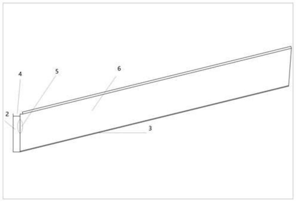
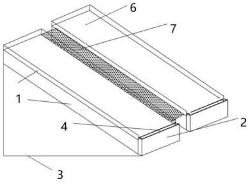
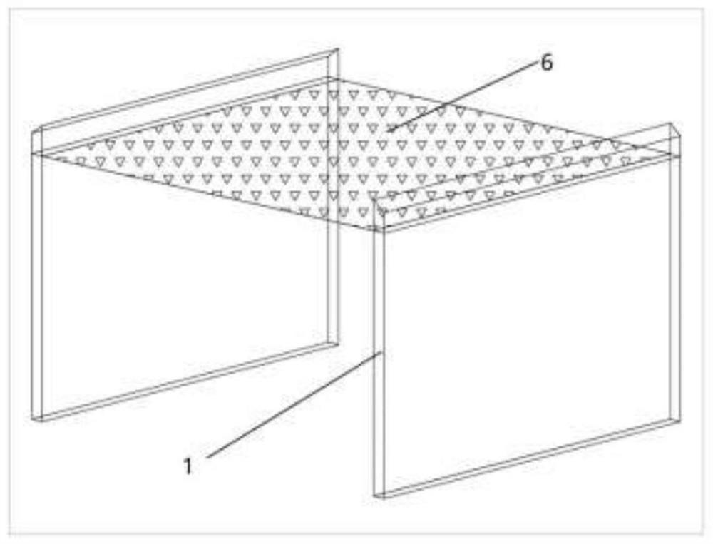
[0023] The present invention works and implements in this way, a test plot for separate monitoring of surface runoff on field slopes and layered soil middle flow, mainly including ridge 1, retaining wall 2, bottom plate 3, collecting tank 4 and underground stratification Soil middle flow converging device 5 is characterized in that: surrounding ridge 1, earth retaining wall 2 and underground base plate 3 enclose the soil 6 of the test plot, the left and right ends and the top of the test plot are provided with enclosing ridge 1, and the lower end is provided with retaining wall 2. The bottom plate 3 is located at the bottom of the soil in the test plot, and the surface runoff collection tank 4 is provided on the lower retaining wall.

[0024] Further, an isolation zone 7 is set between the test plots and between the test plots and the outside, and the test plots are slopes; a 1.5m-wide isolation zone 7 composed of Pseudomonas grass is set between different test plots. Pseudomo...


PUM

PropertyMeasurementUnit
Thicknessaaaaaaaaaa

Abstract

The invention discloses a test plot for separately monitoring field slope surface runoff and interflow. The test plot is characterized in that an enclosing ridge, a retaining wall and an underground bottom plate enclose the soil of the test plot, surrounding ridges are arranged at a left end, a right end and a top end of the test plot, a retaining wall is arranged at the lower end of the test plot, the bottom plate is located at the bottommost layer of soil of the test plot, a surface runoff collecting tank is arranged between the lower end of the test plot and the retaining wall, and an underground layered interflow collecting device is arranged below the soil of the test plot and above the bottom plate. The test plot is advantaged in that a complete device for collecting the surface runoff and the interflow is supplemented, the surface runoff and the interflow of different layers are guided out separately, the surface runoff can be collected and guided out without errors, meanwhile,a problem that the interflow cannot be guided out accurately originally can be solved, and the interflow of each layer can be collected accurately.

Description

technical field [0001] The invention relates to a monitoring test device, which belongs to the field of water and soil conservation, in particular to a field large-scale surface runoff and soil midflow collection monitoring test device. Background technique [0002] Runoff is formed by atmospheric precipitation and enters a river, lake or ocean through different paths within a watershed. Runoff can be divided into soil inflow, soil inflow and groundwater flow according to its formation and flow path. Among them, traditional soil and water conservation work focuses on the collection of surface runoff to monitor surface water and soil loss. However, there is a lack of collection of soil inflows, especially stratified soil inflows. The seepage flow formed by rainfall is blocked and accumulated on the discontinuous interface of the soil layer, forming a temporarily saturated zone and forming a soil inflow. When the soil has a layered structure and the infiltration capacity of...

Claims


Application Information

Patent Timeline
IPC IPC(8): G01F1/00G01N33/24
CPCG01F1/002G01N33/24
Inventor 张龙陈晓安谢颂华刘艳王农杨洁郑海金谢林波冯阳
Owner 江西省水利科学院
Why Eureka
Try Eureka